


13
Section 3: Adjustments
12/09/15
AR2596 & AR2510 Pasture Aerators 325-127M
Table of Contents
Section 3: Adjustments
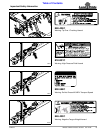
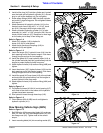
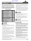
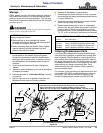
Hitch Height
Refer to Figure 3-1:
Cat. IV hitch (#5) can be raised or lowered to suit. Hitch in
Figure 3-1 is shown being installed in the highest
position. Use this location for tractors with a high
drawbar. Use the lower mounting location for tractors
with a lower drawbar.
1. With tongue supported by the support jack (#4),
remove cap screws (#2).
2. Align Cat. IV hitch with the top two holes or with the
bottom two holes as needed.
3. Insert 1"-8 x 7" GR5 cap screws (#2) through
mounting holes in hose holder (#1), nearside holes in
the tongue, mounting holes in Cat. IV hitch (#5), and
out through the far side holes in the tongue.
4. Secure cap screws with nylon insert nuts (#3).
Tighten nuts to the correct torque.
Hitch Height Adjustment
Figure 3-1
30076
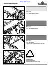
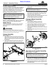
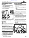
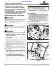
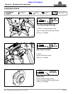
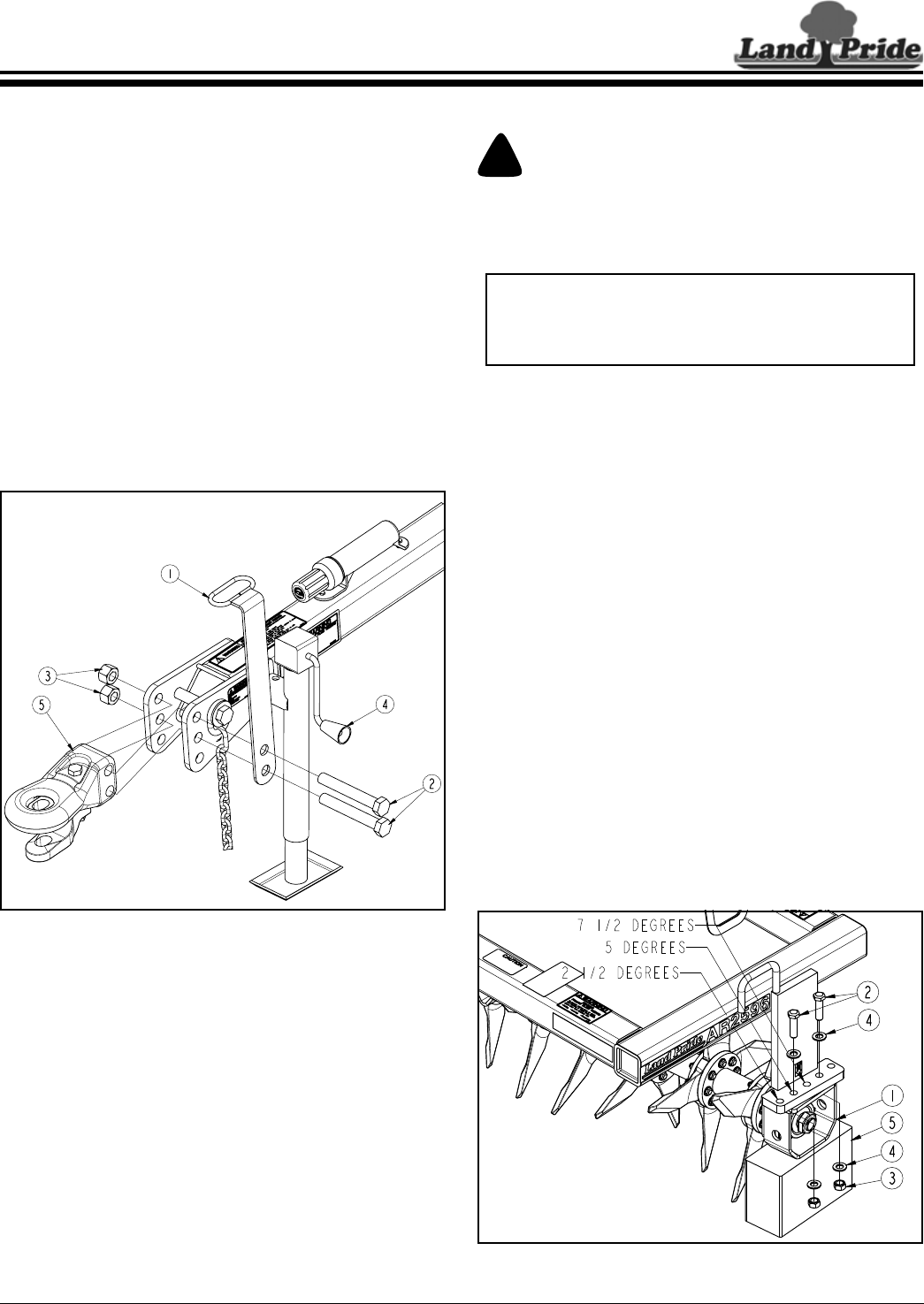
Rotor Tine Gang Angle
!
WARNING
Keep everyone clear of the rotor tines while adjusting tine
gang angle. Removing bolts to adjust tine gang angle will
allow the gang to drop if not properly supported. Body
extremities can be injured should the gang drop.
The tine gang angle can be adjusted to 2 1/2
o
,5
o
& 71/2
o
.
The greater the angle the greater the cultivation action on
the soil.
Refer to Figure 3-2:
1. Park on a flat level surface, engage park brake, raise
Aerator until tines are approximately 1" off the
ground, shut tractor engine off, and remove key
before dismounting from tractor.
2. Place support block (#5) under bearing guard (#1) to
keep the rotor tine gang from falling. Do not force
support block tight against the bearing guard as
this will making adjusting the gang angle difficult.
3. Loosen both hex top lock nuts (#3) until bearing
guard (#1) is resting on support block (#5).
4. Remove hex top lock nuts (#3), cap screws (#2), and
flat washers (#4).
5. Slide gang on the support block to one of the three
positions where the front gang hole in bearing guard
aligns with one of the selected three front mounting
holes (2 1/2
o
, 5
o
, or 7 1/2
o
) in the bearing support.
6. Reinstall 3/4"-10 x 2 3/4" GR5 cap screws (#2), flat
washers (#4), and hex top lock nuts (#3). Tighten
nuts to the correct torque.
7. Repeat steps 2 to 6 for the other rotor tine gang.
Tine Angle Adjustment (5 Degrees Shown)
Figure 3-2
IMPORTANT: For safety, it is best to make
adjustments to the gang angle with the Aerator
raised just enough to support the tines off the
ground by not more than 1".
30067