


8
Section 1: Assembly & Set-up
AR2596 & AR2510 Pasture Aerators 325-127M
12/09/15
Table of Contents
Section 1: Assembly & Set-up
Tractor Requirements
The tractor horsepower and weight must be capable of
controlling the Aerator under all operating conditions.
The Aerator is designed to be used on 40 to 90 hp
tractors with a standard drawbar or with a hammer strap
drawbar. Tractors smaller or larger than the rated
horsepower range must not be used.
Torque Requirements
Refer to “Torque Values Chart”page 24 to determine
correct torque values when tightening hardware.
Dealer Set-up
The pull type Aerator is shipped partially assembled.
Some components will need be assembled at the
dealership.
!
WARNING
The Aerator is top heavy. Make sure Aerator is properly
supported under the upper square tube frame to keep unit from
rotating on its tines during assembly and set-up. Otherwise,
the unit could rotate and cause serious injury.
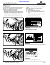
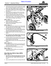
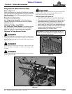
Tongue Assembly
Refer to Figure 1-1:
1. Apply silicone caulk to the surfaces on the plastic
plugs (#5) that mate with square tube ends where the
plugs are to be inserted into. (Silicone caulk supplied
by customer.)
2. Insert plastic plugs (#5) into the four square tube
openings at the four corners of the main frame.
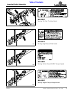
Tongue Assembly
Figure 1-1
NOTE: Front tractor weights and/or ballast to tires
may be required to offset weight of Aerator. Consult
your tractor manual for instructions on installing
additional ballast weights to your tractor.
30058
3. Insert tongue (#2) approximately 34" into receiver
opening (#1).
4. Attach tongue to the receiver tube by inserting 1" x 5"
clevis pin (#4) from the right side. Secure clevis pin
with cotter pin (#3). Bend one or more legs of the
cotter pin to keep it from falling out.
5. Remove jack stand (#7) from top mount stob “A” and
attach to side mount stob “B” with detent
pin (#6). Make sure pin is fully inserted.
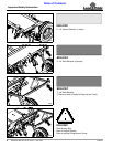
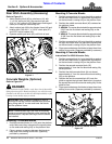
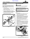
Transport Wheel Assembly
Refer to Figure 1-2:
1. Orient transport wheels (#1) with valve
stems (#8) facing in towards the center.
2. Attach transport wheels to axle hubs (#7) with lug
bolts (#4). Tighten bolts to the correct torque.
3. Attach cylinder stop (#2) to rear axle with wire
retaining pin (#5). Make sure wire retainer is secured
over the pin.
4. Attach five cylinder stops (#6) to the other rear axle
gusset plate.
Wheel & Axle Assembly
Figure 1-2
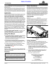
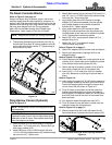
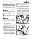
Rear Axle & Lift Cylinder Assembly
Refer to Figure 1-3 on page 9:
1. Attach rear axle assembly (#1) to the Aerator’s main
frame with 7 1/4" long pivot pins (#2). Make sure the
grease zerks on pins (#2) face out and lug (#1) is up.
2. Secure pivot pins with 5/16"-18 x 2" GR5 hex head
cap screws (#4) and lock nuts (#5). Tighten nuts to
the correct torque.
IMPORTANT: Clevis pin (#4) must be inserted from
the right side as shown in Figure 1-1.
30059
IMPORTANT: Insert zerk end of pivot pins (#2) in
first as shown. Protect zerks when hammering on
pins by hitting pins on the end without a zerk.