


9
Section 1: Assembly & Set-up
12/09/15
AR2596 & AR2510 Pasture Aerators 325-127M
Table of Contents
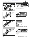
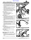
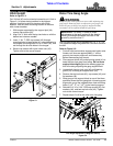
3. Install orifice plug (#12) into the cylinder port located
near the base end of hydraulic cylinder (#11). Screw
plug in until orifice bottoms out. Do not tighten.
4. Screw elbow fittings (#9A & #9B) into both cylinder
ports with O-rings facing ports. Do not tighten elbows
until step #17.
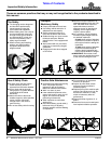
5. Attach base end of hydraulic cylinder (#11) to the
Aerator’s main frame (#3) with 1" x 3 11/16" clevis
pin (#10). Secure pin with hairpin cotter (#8).
6. Attach rod end of hydraulic cylinder (#11) to axle
assembly (#1) with 1" x 2 3/4" clevis pin (#6). Secure
clevis pin with cotter pin (#7). Bend one or more legs
on the cotter pin to keep it from falling out.
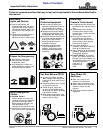
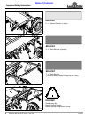
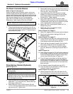
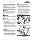
Refer to Figure 1-4:
7. Attach 3/4" adapter (#18) to hydraulic
hoses (#13 & #14) and tighten.
8. Attach quick disconnect couplings (#19) to
adapters (#18) and tighten.
Refer to Figure 1-3:
9. Insert the longer (201") hydraulic hose (#14) into the
back opening end of the Aerator tongue. Push hose
through tongue and out its front opening.
10. Install flex guard (#15) over hydraulic hose (#14) at
the cylinder end and push flex guard halfway into the
tongue to protect hydraulic hose from wear.
11. Attach hydraulic hose (#14) to elbow fitting (#9B) and
tighten.
12. Insert the shorter (185") hydraulic hose (#13) into the
back opening end of the Aerator tongue. Push hose
through tongue and out its front opening.
13. Install flex guard (#15) over hose (#13) at the cylinder
end and push flex guard halfway into the tongue to
protect hydraulic hose from wear.
14. Attach hydraulic hose (#13) to elbow fitting (#9A) and
tighten.
Refer to Figure 1-4:
15. Pull hydraulic hoses (#13 & #14) out of opening (#17)
until most of the slack in the hoses at the hydraulic
cylinder have been removed.
16. Run hydraulic hoses through hose loop (#16).
Refer to Figure 1-3:
17. Orient elbows (#9A & #9B) to suit and tighten to
hydraulic cylinder (#11).
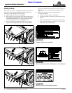
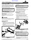
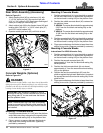
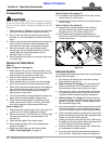
Slow Moving Vehicle Sign (SMV)
Refer to Figure 1-5:
1. Bolt SMV sign (#3) to mounting blade (#4) as shown
with 1/4"-20 x 5/8" GR5 hex flange screws (#1) and
hex flange nuts (#2). Tighten nuts to the correct
torque.
2. Insert mounting blade (#4) into mounting socket (#5).
Rear Axle & Lift Cylinder Assembly
Figure 1-3
Hydraulic Hose Routing & Quick Coupling Assembly
Figure 1-4
Slow Moving Vehicle Sign Assembly
Figure 1-5
30060
Grease Zerk
Grease Zerk
30061
30062