


ASSEMBLY
OM 0408SB1174-A
25
ASSEMBLY
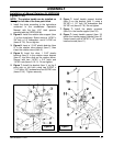
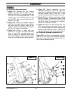
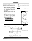
For Chute with knob adjustment:
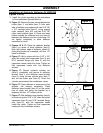
1. Figure 22: Remove the two manual
adjustment knobs and the bolts on each
deflector side (item 11) and replace with two
5/16” NC x 3/4” carriage bolts (item 1), the
original nylon insert locknuts (item 2) and
two 5/16"NC nylon insert locknut (item 3).
Leave a 1/16" play.
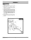
2. Figure 22: Place the deflector bracket
(item 5) in the middle of the chute deflector,
and align with the bottom edge of the
deflector. Using the bracket as a template,
drill four 1/2" holes in the deflector.
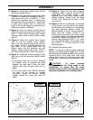
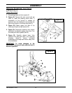
3. Figure 22: Secure in place with four
5/16" NC x 3/4" allen flat head setscrews
(item 4) and 5/16" serrated flange nuts
(item 6), placing the setscrew head inside
the chute. Tighten until the setscrew head
sinks into the inside surface of the deflector.
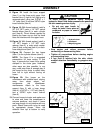
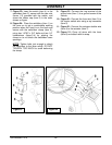
4. Figure 22: Retract completely the pre-
assembled actuator rod (item 10). Attach the
actuator to the deflector bracket (item 5) and to
the base bracket (item 7), with two 1" pins
(item 8) and secure with two hairpins (item 9).
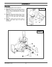
5. Figure 22: Open deflector completely, making
sure the actuator is completely closed. Place
the base bracket (item 7) in the rear center of
the chute. Using the bracket as a template,
drill four 1/2" holes in the chute.
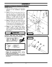
6. Figure 22: Attach the base bracket with four
5/16" allen flat head setscrews (item 4) and
5/16" serrated flange nuts (item 6) placing the
setscrew head inside the chute. Tighten until
the setscrew head sinks into the inside surface.
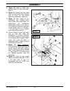
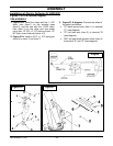
For Chute with telescopic adjustment rod:
Figure 22A: Install the pre-assembled actuator
(item 10) on the chute in the illustrated position
with two 1" pins (item 8) and secure with two
4mm x 80mm hairpins (item 9).
Figure 22 Figure 22A