


ASSEMBLY
OM 0408SB1174-A
24
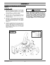
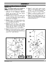
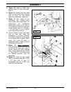
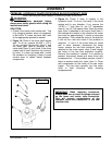
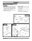
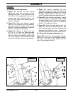
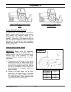
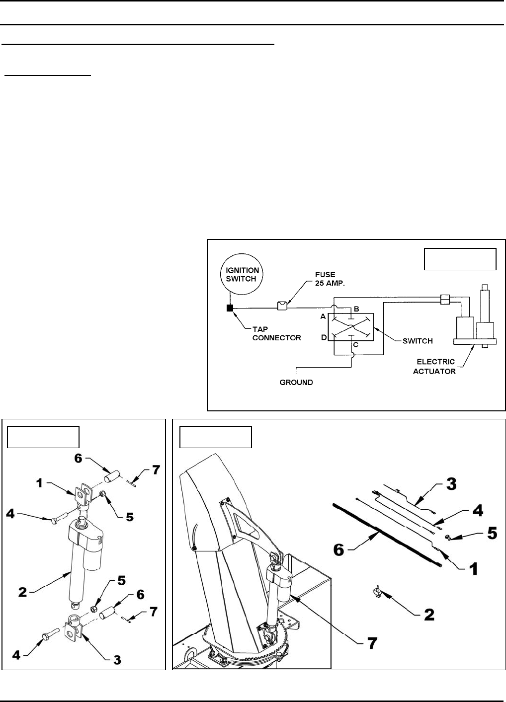
Figure 21 Figure 21A
Diagram
Installation of Electric Deflector Kit 5RDF0021
(Figures 21 to 24 & Electrical Diagram)
PRE-ASSEMBLY
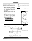
1. Figure 21A: Install the clevis with the 1 1/32"
diam. hole (item 1) on the actuator base
(item 2), and the one with the 1 5/32" diam.
hole (item 3) on the other end and attach
using two 1/2" NC x 2 1/2" bolts and two 1/2"
NC nylon insert locknuts (items 4-5).
2. Figure 21A: Install a 3/16" x 1 3/4" spring pin
(item 6) on each 1" pin (item 7).
3. Figure 21 & diagram: Connect the wires to
the switch as follows:
• 72" black ground wire (item 1) to terminal
"C" (see diagram).
• 72" red fuse wire (item 3) to terminal "B
(see diagram).
• 360" red and black actuator wires (item 4)
to terminal "A" and "D" (see diagram).