


ASSEMBLY
OM 0408SB1174-A
21
PROBLEM: HYDRAULIC CHUTE ROTATION IS SLOW OR DOESN'T TURN
When activating the chute rotation, it turns very slowly or not at all.
WARNING
To avoid serious personal injury
,
always wear safety glasses while doing the
instructions below.
SOLUTION:
1. Check if the tractor valve works well. Test
it by plugging another piece of equipment
to the valve. If it does not work well, refer
to the appropriate operator's manual.
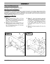
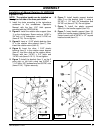
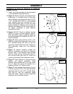
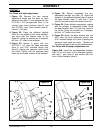
2. Figure 14: Check if the chute itself rotates
well. To do so, remove the M6 x 1.00 x
10 mm serrated flange bolt (item 7) and
the motor gear (item 6) attached to the
motor shaft (item 4) and check if the chute
rotates well in both directions by turning it
by hand. If it does not rotate well, correct
the problem by checking if there is some
excess wear or debris locked between
components.
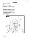
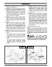
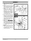
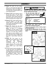
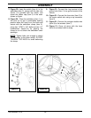
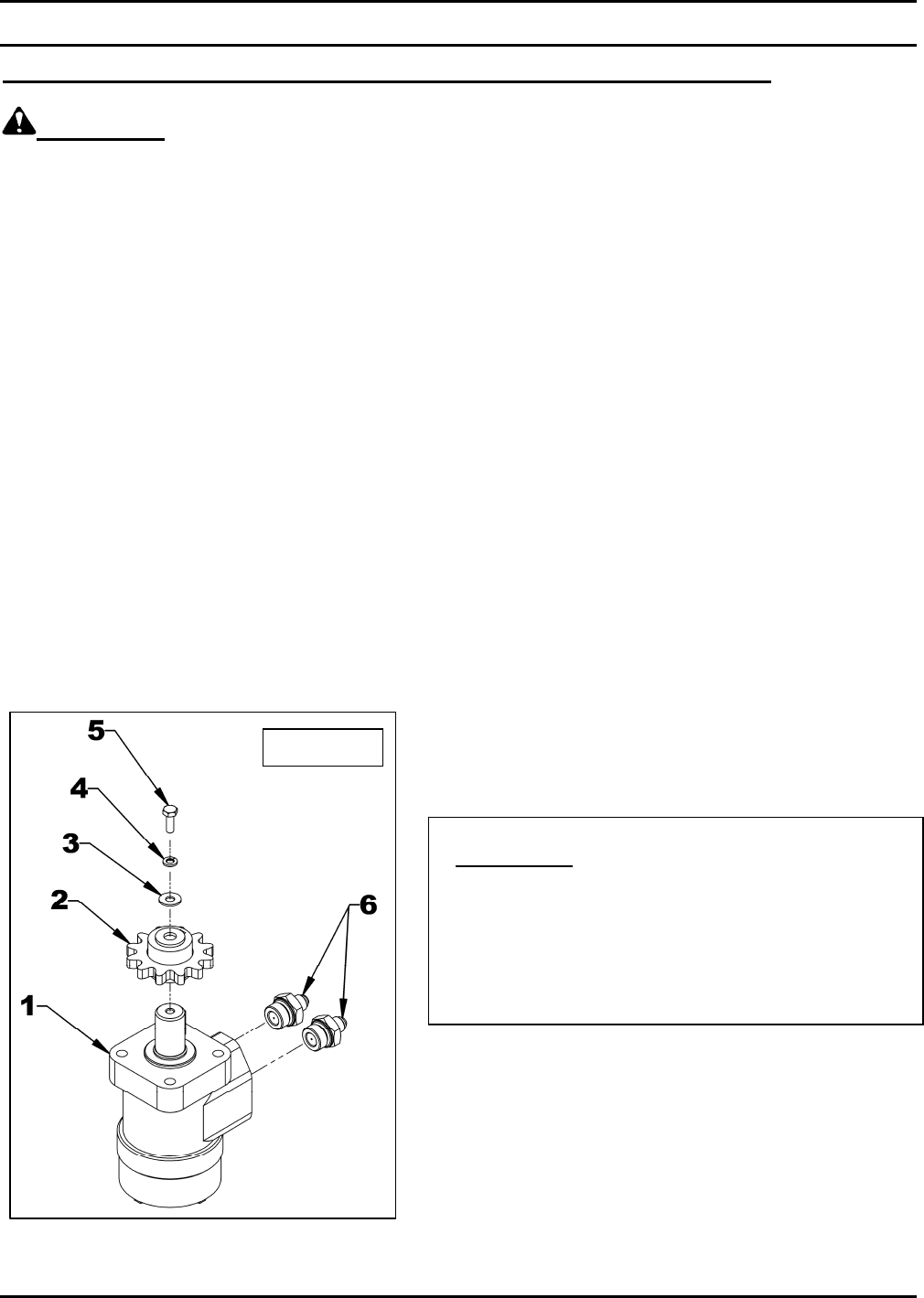
3. Figure 14: Check if there is residue in the
hydraulic circuit. To do so, first verify if the chute
rotates well in one direction. If so, remove the
1/4’’NC x 1’’ bolt (item 5), the 1/4" lockwasher
(item 4), the 1/4" flat washer (item 3)and the motor
gear (item 2) attached to the motor shaft (item 1)
and activate the rotation in the direction the motor
turns well for approximately 1 minute to evacuate
the residues. Then rotate the chute in the direction
it did not turn well and check if the problem is
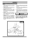
resolved. - If not or if the chute does not rotate
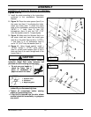
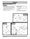
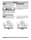
well in either direction, disconnect the motor
hoses, remove the two flow restrictors (item 5)
attached to the motor inputs (item 2) and inspect
the holes of the two flow restrictors carefully.
Remove the residues if needed. If no residue is
present, disconnect hoses and clean them with
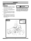
compressed air. - If the problem persists, check if
there is residue inside the motor (item 1). Clean
with compressed air the inside of the two motor
inputs. You can also manually turn the motor
shaft in both directions while shooting
compressed air.
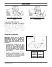
IMPORTANT
: When removing connectors,
always make sure to install the plugs and caps
on the hoses and tractor valve connectors.
This will prevent contamination of the
hydraulic circuit and obstruction of the flow
restrictor hole.
Figure 14