


ASSEMBLY
OM 0408SB1174-A
19
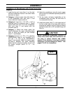
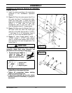
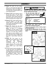
1. Hydraulic hose
2. Cardboard
3. Ma
g
nif
y
in
g
g
lass
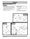
Installation of Hydraulic Rotation Kit 5RDF0047
(Figures 10 to 14)
1. Install the chute according to the instructions
contained in the snowblower Operator's
Manual.
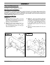
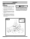
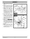
2. Figure 10: Place the motor spacer (item 2) on
the motor top (item 1) by aligning the holes.
Install the motor (item 1) under the frame
base of the snowblower and secure with four
3/8’’NC x 1’’ bolts (item 3), four 3/8"
lockwashers (item 4) and four 3/8" (7/16"
hole) flat washers (item 5). Torque slightly.
3. Figure 10: Make sure the Woodruf key is on
the motor shaft and insert the motor gear
(item 6) on the shaft. Secure with a 1/4’’NC x
1’’ bolt (item 7), a 1/4" lockwasher (item 8)
and a 1/4" (5/16" hole) flat washer (item 9).
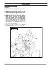
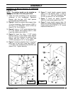
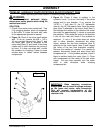
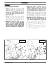
4. Figure 11: Using thread sealant, install a
1/4"NPT female x 1/2"NPT male reducer
(item 2), a male quick coupler (item 3) and a
dust cap (item 4) on each straight end of the
hoses (item 1).
CAUTION
To avoid serious personal injury. Escaping
hydraulic/ diesel fluid under pressure can
penetrate the skin causing serious injury.
• Do not use your hands to
check for leaks. Use a
piece of cardboard or
paper to search for leaks.
• Stop engine and relieve pressure before
connecting or disconnecting lines.
• Tighten all connections before starting
engine or pressurizing lines.
• If any fluid is injected into the skin, obtain
medical attention immediately or gangrene
may result.
Figure 10
Figure 11