


ASSEMBLY
OM 0408SB1174-A
18
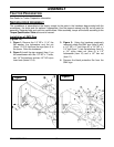
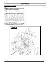
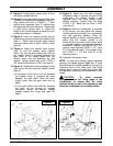
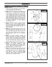
9. Figure 8: Install plastic handle (item 5) over
the rotation handle (item 6).
10. Figure 8: Insert assembled rotation tube (item
1) inside the rotation worm assembly (items 2).
Align holes and insert a 10-24NC x 1’’ allen
socket head capscrew (item 3) making sure
the capscrew sinks into the worm. Secure with
a nylon insert locknut (item 4). Adjust the
height of the handle support according to your
needs and shorten if necessary.
11. Figure 8: Insert the rotation handle (item 6)
inside the grommet and inside the rotation tube
(item 1). Select desired length, align nearest
holes and secure with a 4mm x 80mm hairpin
(item 8).
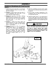
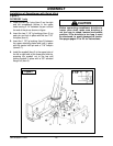
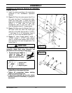
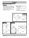
12. Figure 9: Adjust the rotation tube support
(item 3) and the rotation worm support
(item 1) by moving them toward the chute so
the rotation worm is engaged between the
gear teeth of the chute. Make sure the
rotation worm and the bushings are well
aligned. Tighten slightly the three 1/4"NC x
3/4" bolts and the three 1/4"NC nuts (item 2).
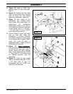
13. Figure 9: Rotate the chute completely to the
right then to the left using the rotation handle
(item 4).
• If the chute is too hard to turn it's because
the rotation worm is engaged too deep
between the gear teeth, move the worm
slightly away from the gear teeth and try
again.
• If the chute rotates with difficulty because
the teeth do not engage or engage
incorrectly, adjust the rotation handle
support toward the chute and redo the
steps.
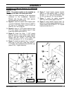
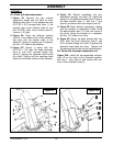
14. Figure 9: Make sure the worm engages
completely when it reaches the end of the
chute gear. The rotation handle is well
adjusted when the chute rotates easily
without straining. Tighten firmly the three
1/4"NC x 3/4" bolts and the three 1/4"NC
nuts (item 5).
15. Figure 9: After the snowblower is mounted
to the tractor, you may adjust the rotation
handle position and height to a comfortable
and safe operating position. When the
desired position is set for working position,
make sure the rotation handle is not
interfering with any parts of the tractor while
on transport position (snowblower raised to
maximum). Tighten firmly the 3/8"NC x 1/2’’
square head setscrew 3/8"NC x 1/2" (item
5) to the desired height. Then tighten firmly
the 3/4"NC x 1 1/2" bolt (item 6) to the
desired position.
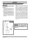
16. Lubricate the rotation worm.
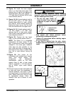
NOTE: To insure the manual rotation operates
properly, the handle support (fig.8, item 7) must
be positioned the closest possible to the top link
mounting point of the three point hitch while
making sure it does not come into contact with
the operator's seat when the snowblower is fully
raised.
CAUTION: To avoid personal
injury, check the full lifting range of the
snowblower, to ensure that the chute
rotation handle is clear of the operator’s area
when the snowblower is in raised position.
Fi
g
ure
8
Fi
g
ure 9