


ASSEMBLY
OM 0408SB1174-A 20
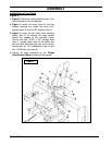
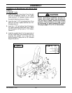
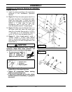
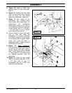
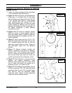
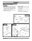
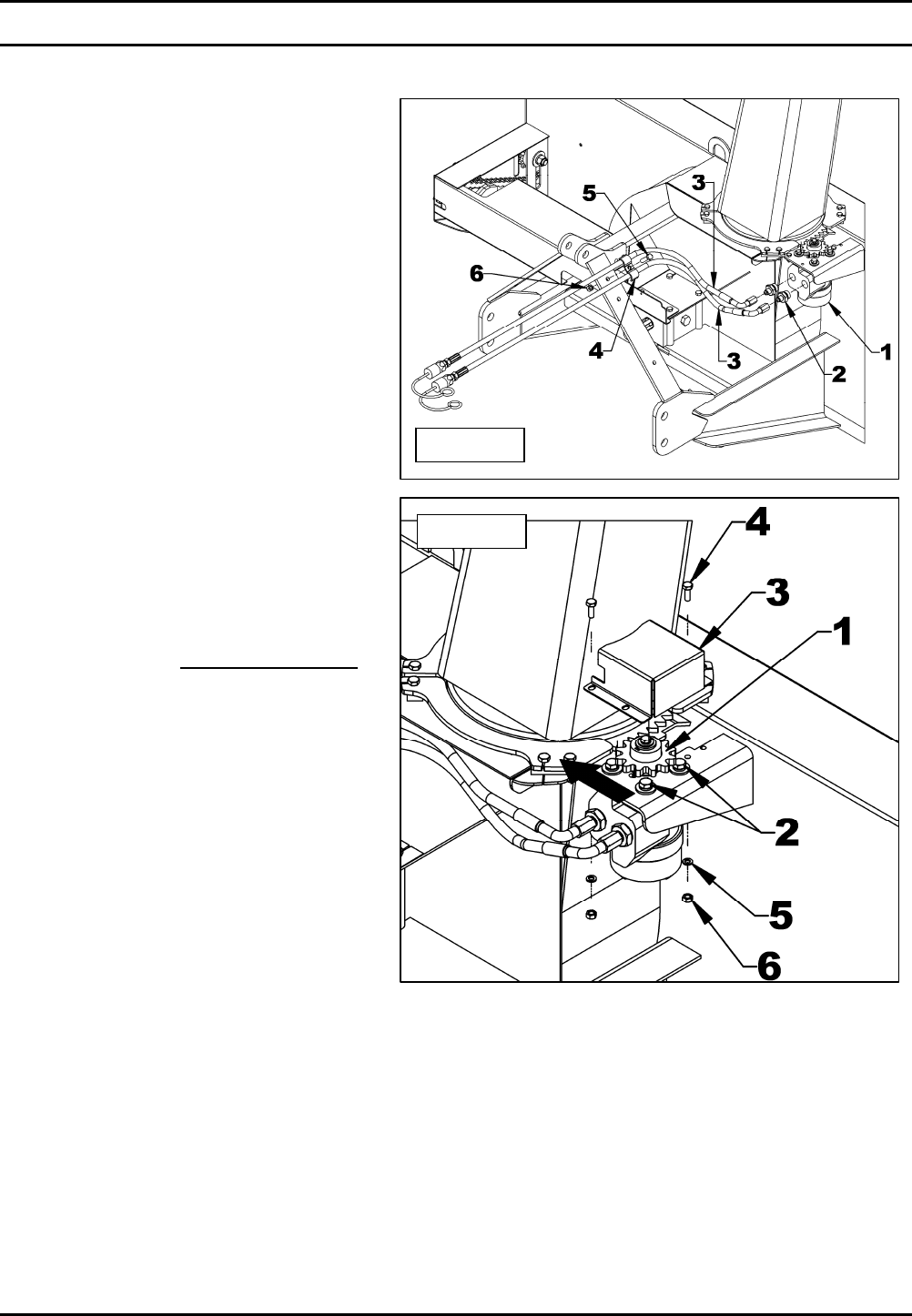
5. Figure 12: Install a 0.052" flow
restrictor (item 2) in each motor input
(item 1).
6. Figure 12: Connect the two hoses
(item 3) on the motor flow restrictors
(item 2). Direct the hose elbows
toward the snowblower upper arm.
7. Figure 12: Run hoses on the
snowblower with suitable bend,
staying away from sharp edges, nor
compromise the snowblower
maintenance. Attach to the right or
left snowblower three point arm with
a hose clamp (item 4), a 3/8"NC x
1 1/2" bolt (item 5) and a 3/8"NC
nylon insert locknut (item 6).
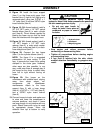
8. Connect hoses to tractor and make
sure to raise and lower the
snowblower in extreme positions,
and check if hoses are long enough
to not interfere with any parts. Attach
hoses with nylon tie wrap to
appropriate places. Rotate the chute
to the right and to the left.
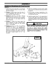
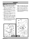
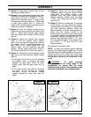
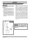
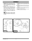
9. Figure 13: Motor adjustment
:
Push the motor toward the chute as
to well set the gear teeth (item 1)
without leaving any play between
teeth. Firmly tighten the four 3/8"NC
x 1" bolts (item 2). If the rotation does
not operate correctly, redo the
adjustment.
10. Figure 13: Install the gear shield
(item 3) and secure with two 1/4"NC
x 3/4" bolts (item 4), two 1/4"
lockwashers and two 1/4"NC nuts
(items 5-6), as illustrated.
Figure 12
Figure 13