


Page 12
J-400
4. The electrical supply for this product must include a suitably rated
switch or circuit breaker to open all ungrounded supply conductors to
comply with Section 422-20 of the National Electrical Code/USA,
ANSI/NFPA 70. The disconnecting means must be readily accessible
to the spa’s occupant but installed at least 5 feet (1.5m) from spa
water.
5. The electrical circuit supplied for the spa must include a suitable
ground fault circuit interrupter (GFCI) as required by NEC Article
680-42/USA.
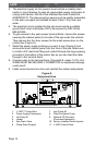
6. To gain access to the spa’s power terminal block, remove the screws
securing the cabinet panel on the side of the spa under the controls.
Then remove the four door screws for the small access door on the
control box (Figure A).
7. Select the power supply entrance you want to use (Figure A) and
remove the short cabinet panel from the front of the spa. Make sure
to install a 3/4" electrical tting and conduit through the large opening
provided in the bottom of the control box so you can feed the cable
through to the terminal block.
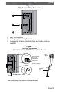
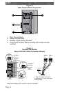
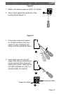
8. Connect wires to the terminal block (Figures B-E, pages 13-15). ALL
WIRES MUST BE SECURELY CONNECTED or equipment damage
could result!
9. Install control access box door and reinstall the cabinet side panels.
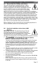
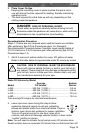
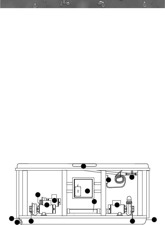
Figure A
Equipment Area
10
4
2
2
Flow
Note: Pump Locations Vary by Model
5
6
6
9
8
7
6
3
1
11
Access Door
1. J-1000™ Control Box
2. Power Supply Entrance(s)
3. Jet Pump #1
4. Heater
5. Spa Drain Valve
6. Pump Drain Plugs(s)
7. Jets Pump #2
8. Filter/Circulation Pump
9. Optional CD Ozonator
(Purchase Separately)
10. Factory Installed Ozone Injector
11. J-1000 Control Panel