


Jacuzzi Whirlpool Bath: Finestra Walk-in Bath Page 5 FL61000B • 10/07
SPECIFICATIONS
Important: Read complete instructions before beginning installation.
Each whirlpool bath arrives ready for installation, completely equipped with motor/pump assembly, heater, plumbing, and ttings
necessary for whirlpool operation. A rotary drain/overow kit is provided for installation on the bath, and an optional remote drain/
overow assembly is also available.
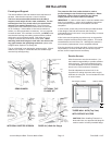
Remove the bath from the carton. Retain the shipping carton until satisfactory inspection of the product has been made. Do not lift
the bath by the plumbing at any time; handle by the shell only or the aluminum handles provided at the ends of the unit.
Immediately upon receipt, inspect the shell before installing. Should inspection reveal any damage or defect in the nish, do not
install the bath. Damage or defect to the nish claimed after the bath is installed is excluded from the warranty. Jacuzzi Whirlpool
Bath’s responsibility for shipping damage ceases upon delivery of the products in good order to the carrier. Refer any claims for
damage to the carrier. For denitions of warranty coverage and limitations, refer to the published warranty information packed with
the product.
All bath units are factory tested for proper operation and watertight connections prior to shipping.
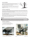
NOTE: Prior to installation, the bath must be lled with water and operated to check for leaks that may have resulted from shipping
damage or mishandling. Jacuzzi Whirlpool Bath is not responsible for any defect that could have been discovered, repaired, or
avoided by following this inspection and testing procedure.
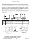
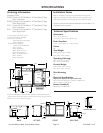
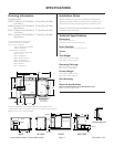
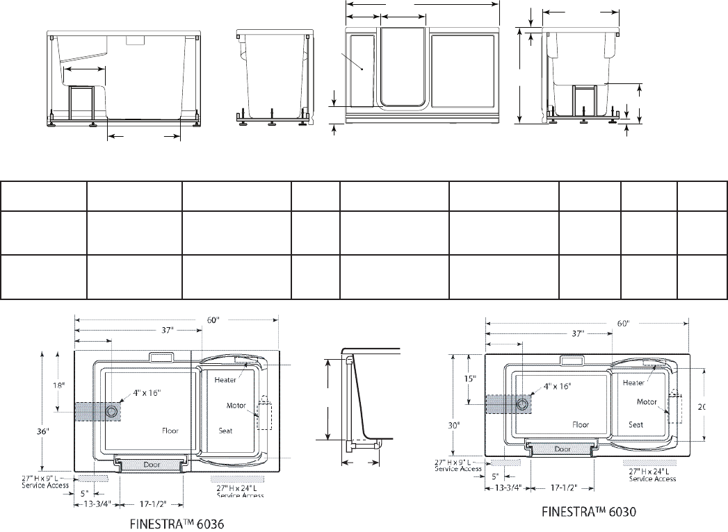
* Add 1/4" to this dimension when roughing-in for 3-wall niche.
FOR ALL UNITS: Electrical Service Requirements: All require a dedicated GFCI protected separate circuit ( See page 7 to 12).
NOTE: 1. Measurements inside each unit represent cutout in oor to allow for drain/overow.
2. All measurements are in inches. To convert to millimeters, multiply inches by 25.4.
3. Service access dimensions given are minimum size.
4. The overall dimensions are nominal with a tolerance of +0 and -1/4" (6.4 mm).
Model
Dimensions
Drain/Overow
Dimensions
Cutout
Total Weight/Floor
Loading
Operating
Gallonage
Product
Weight
Skirt/
Mounting
Heater
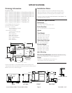
Finestra™ 6030
LH, RH
60” (1524 mm) L
30” (762 mm) W
38-1/2” (952.5) H
15” (381 mm) A
11-11/16” (297 mm) B
See
below
1038 lb (472 kg),
41.5 lb/ft
2
(202 kg/m
2
)
55 gal (208 liter) min,
75 gal (284 liter) max
See pages
6 to 11
Integral Factory
installed
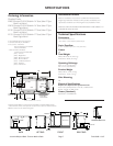
Finestra™ 6036
LH, RH
60” (1524 mm) L
36” (914 mm) W
38-1/2” (952.5) H
18” (457 mm) A
11-11/16” (297 mm) B
See
below
1177 lb (535 kg),
47.1 lb/ft
2
(229 kg/m
2
)
55 gal (208 liter) min,
85 gal (321 liter) max
See pages
6 to 11
Integral Factory
installed
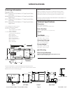
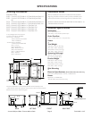
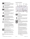
DRAIN/OVERFLOW
A
B
BACK FRONTLEFT END RIGHT END
L
H
W
14"
1-1/2"
2"
6-1/2"
29-1/2"
16-3/4"
17-1/2"
13-3/4"
Service Access
Service
Access
SPECIFICATIONS LH=Left Hand, RH=Right Hand
11-11/16"
11-11/16"