


Jacuzzi Whirlpool Bath: Finestra Walk-in Bath Page 23 FL61000B • 10/07
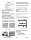
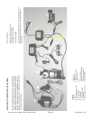
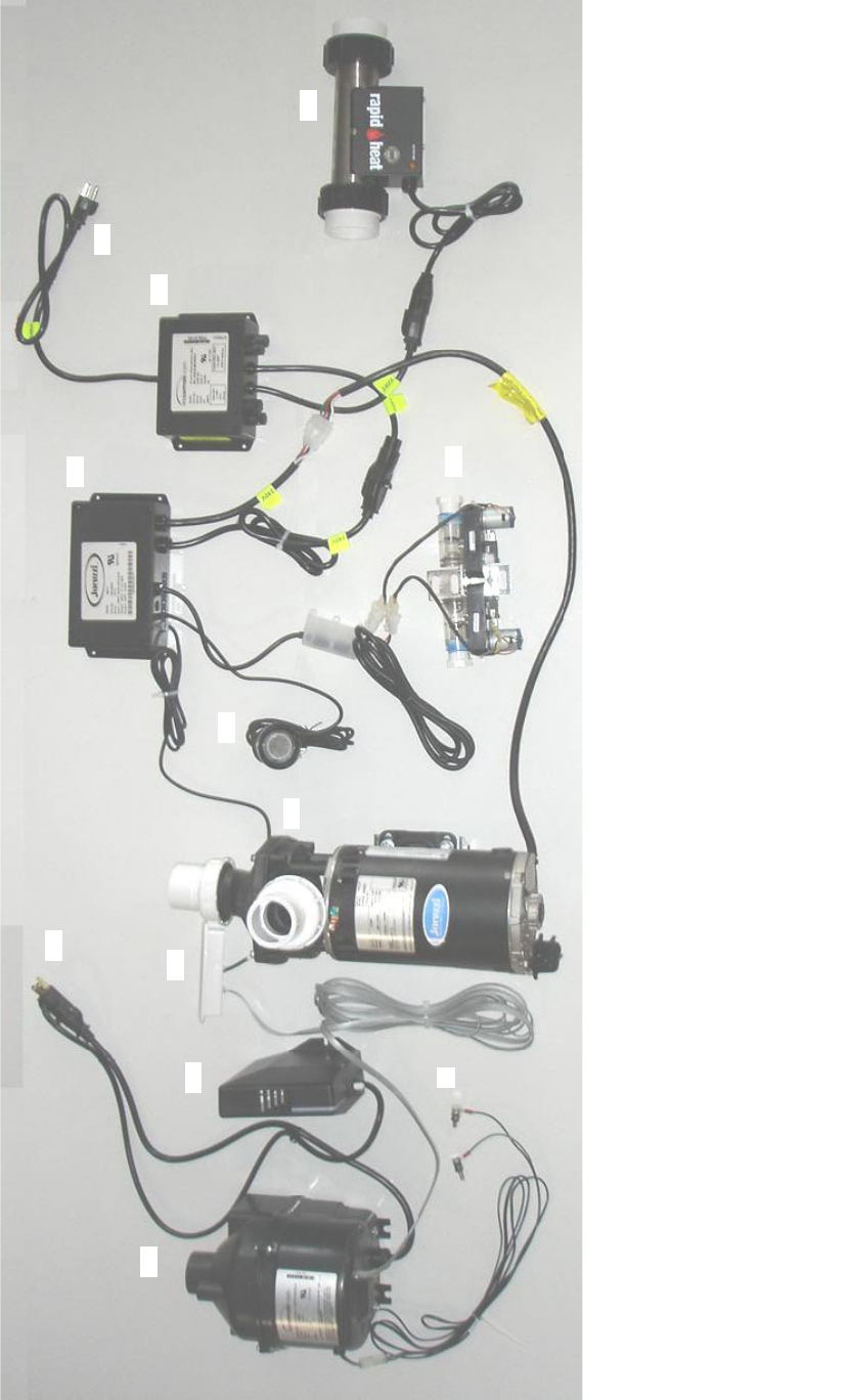
SALON BATH INTERCONNECTION DIAGRAM
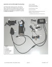
The Salon bath equipment is shown in the following gure.
It shows the only acceptable manner in which the system
components may be interconnected for efcient and safe
operation. If the equipment is not congured as shown in
the gure, the equipment may not operate or it may result
in damage to the equipment
I Fuse box
J RapidHeat™
K Electronic air switch
L Water sensors
----------
*PLug into separate
dedicated GFCI receptacle
**Plug into separate GFCI
protected breaker
C
D
A
F
G
E
I
J
K
L
B
H
LEGEND
A Blower
B GFCI Receptacle, 15 A*
C Ozone system
D Control panel
E Pump/motor
F Chromatherapy light
G Control box
H GFCI Plug, 230 V, 20 A**
MODEL NUMBERS
EW05, EW10, EW30, EW35, EW40,
EY30, EY35, EY70, and EY75
See Specications for details
ELECTRICAL SPECS
Requires two separate dedicated GFCI protected separate circuits
Motor/Pump and RapidHeat, 230 VAC, 20 A, 60 Hz RapidHeat,
PN BN60000