


Jacuzzi Whirlpool Bath: Finestra Walk-in Bath Page 12 FL61000B • 10/07
Framing and Support
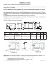
The drain/overow of the bath extends below the bottom of
the bath. Note that this requires a cutout in the oor.
The oor structure beneath the bath must be able to
support a total weight of bath, water, and bather. For the
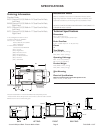
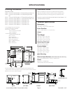
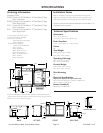
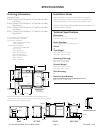
total weight of the unit, please refer to the specication
sheet for your model (pages 5 to 11). The unit must be
supported from the bottom of the bath and not from the bath
rim or tile ange. If the suboor is level and a continuous
surface, no other preparation is necessary. You can proceed
to install the bath. If the suboor is not level, you MUST make
sure that the level legs are making contact with the suboor
and that the unit is perfectly leveled. Both sides of a joint
or splice of suboor should be level to each other. When
attaching baths with anges to stud wall, use shims to ll
any gaps between the bath ange and studs, please refer
to gure below, Optional Tile Flange Kit.
The rim of the bath is not designed to support weight. If nish
material is to overlap or contact the bath, the added weight
must be fully self-supporting.
The protective lm liner inside the bath is used to
prevent damage to the nish during installation. Before
installation, remove liner to inspect for any defects,
reapply and do not remove until nal cleanup.
IMPORTANT: If a skirt is to be used, it must be installed at the
time of unit installation – refer to skirt installation instructions.
Install optional trim parts when all installation has been
completed.
In some cases, access may not have been provided because
of the design of the bath environment and having full
understanding that in this case, it may be necessary to remove
the unit for service.
If this is the case, diagnosing a problem may not be possible
without complete access to the plumbing system. This would
necessitate the removal of the unit. Although this practice is
not commonly implemented, it is an acceptable method.
If service access has not been provided, it is the home owners
responsibility to remove the bath and provide the required
access, should a repair become necessary.
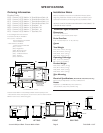
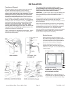
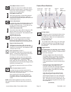
INSTALLATION
SEMI-SUNKEN
Bath
rim
1 x 4” (Not
for support)
Plastic
ller
Stud
wall
Silicone
sealant
Finishing material
Mortar
Nail or
screw
Cement board
Flange
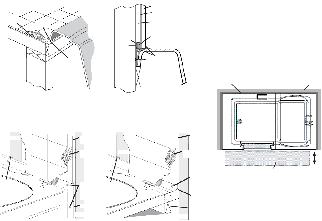
OPTIONAL TILE
FLANGE KIT
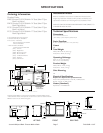
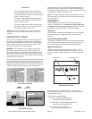
Service Access
Allow for access to service connections. It is
the installer's responsibility to provide sufcient
service access. The recommended minimum
18 inches allowable for service to the bath are
shown in the "Service Access" illustration.
Provide adequate area around unit for air
circulation for cooling the motor and to supply
sufcient air to the jets. Do not insulate this area
or around motor.
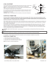
CAUTION: When installing Finestra in a
three-wall niche, an approved tile ange kit
must be used or a factory-installed ange.
THREE-WALL NICH (Top View)
WITH SERVICE ACCESS
18 in
Service Access Required
Walls (3 Sides)Tile Flanges (3 Sides)
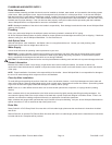
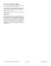
Tile
Sealant
Flashing
Sub-oor
1 x 4” (Not
for support)
Motor or
adhesive
Tile
1/8”
Gap
Flange
Caulking
Shim if
necessary to ll
gaps between
stud and ange
Stud
Stud
Attach
with
screws
provided
Tile
adhesive
Cement
board
Flange
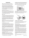
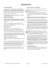
INTEGRAL SKIRTED VERSION DROP-IN (3-Wall tile ange)
1 x 4”
(Not for
support)
Tile
1/8”
Gap
Flange
Caulking
Shim if
necessary to ll
gaps between
stud and ange
Stud
Stud
Attach
with
screws
provided
Tile
adhesive
Cement
board
Flange