


English – 33
MAINTENANCE
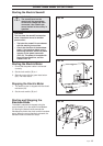
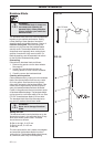
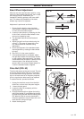
Band Wheel Adjustment
After the one-man saw has been used for a long
period, the band wheel bearings will start to wear
and change position. Meanwhile, the
foundation’s working geometry will have stabili-
sed. This means the parallelism of the band
wheels may need to be adjusted.
Adjustment is performed as follows:
1. Ensure that the electric power has been
disconnected. Unplug the electrical contact
or short-circuit the petrol engine.
2. Loosen the belt tension by releasing the idler
to the V-belt, so that the band wheel is free
and can be rotated by hand.
3. The bandsaw blade should be fitted and
adjusted.
4. Adjust the right-hand band wheel using the
screw (F). The screw is locked with a lock
nut, which should be loosened during
adjustment.
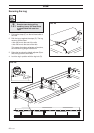
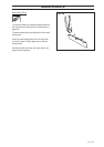
5. Check the alignment of the bandsaw blade
after adjustment by rotating the band wheel
by hand.
6. See FIG. 61 for the correct position.
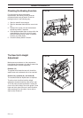
7. If the bandsaw blade is not aligned, adjust
the right band wheel with the spacer located
on the outside of the band wheel. The wheel
is dismantled and the spacer is placed on the
innermost part of the wheel axle and the
wheel is then re-mounted. Repeat steps 2 to
5 until the bandsaw blade is aligned.
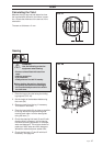
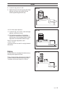
Drive Belt (FIG. 63)
The drive belt wears as the saw is used. The belt
should be replaced after 200 hours of operation
to avoid belt failure during operation. If the drive
slips or the belts need to be frequently adjusted,
this is a sign that the belts need to be replaced.
To replace the belt, proceed as follows:
1. Unplug the electrical contact from the distri-
bution box or short-circuit the petrol engine.
2. Loosen the belt guard.
3. Loosen the idler (A) completely with the
locking lever (B).
4. Change the belt and then tighten the belt by
pulling the handle (C) and tightening the idler
(A) and locking the idler with the locking lever
(B). When the belt is correctly tensioned, it
should be possible to move it about 0.5 cm in
each direction using one finger.
5. Attach the belt guard.
FIG. 63
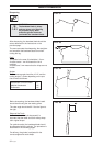
FIG. 61
FIG. 62