20 –English
INSTALLATION
Propulsion
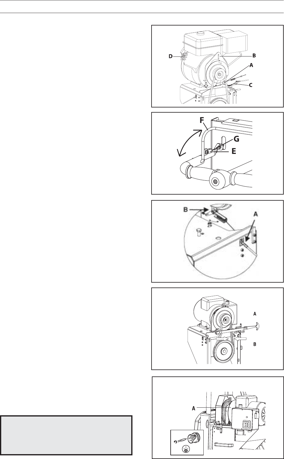
1. Place the engine/motor on the engine/motor
console and attach the drive belt.
2. Bolt the engine/motor (petrol or electric) onto
the engine/motor console.
3. Connect the cable to the clutch control arm
(A).
4. Attach the mounting for the drive disc (B), so
that the clutch does not rotate.
5. Tighten the belt with the belt tension device
(FIG. 31 A). A correctly adjusted belt can be
moved 0.5 cm with one finger (FIG. 31 B). If
necessary, adjust the engine/motor console
mounted in the lengthways slot to attain the
correct belt tension.
6. Connect the cable to the start lever (FIG. 30
E), check that the clutch is activated. When
the start lever (FIG 30 F) is activated, the
spring in the control arm on the clutch shall
be lightly compressed.
Wire adjustment
The wire that engages the clutch must be ad-
justed so that there is no pressure on the clutch
arm that is connected to the clutch. The easiest
way to do this is to adjust the wire so that it is
completely slack when the clutch is not engaged.
Adjustment is by means of the adjuster nipples
on the starter yoke and the engine bracket (FIG
30 G and FIG X A).
It is also important that the attachment to the
clutch is able to swing (FIG X B). The spring in
the fastener prevents excessive leverage being
applied to the clutch arm.
On saw mills with four-stroke engines, the wire
connected to the engine is adjusted using nipple
(FIG X), so that the throttle lever is activated by
the swinging motion (FIG X B) of the wire faste-
ner near the clutch and therefore increases the
engine speed before the clutch is engaged.
Petrol Engine
Connect the cable from the covers’ safety switch
(22) to the contact (FIG. 29 D) on the engine.
Electric Motor
Connect the cable from the covers’ safety switch
to the contact on the distribution box (FIG. 32 A).
The contact for the electrical cable for the electric
motor has polarity reversal (31). Make sure that
the main switch (34) is set to 0.
WARNING!
Check that the main switch is
set to 0, and be sure to invert
the phase if the sawmill runs in
the wrong direction.
!
FIG 29
FIG 30
FIG 31
FIG 32
FIG X


