


English – 11
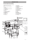
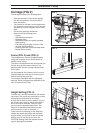
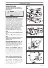
Carriage (FIG 2)
The carriage consists of the following parts:
• Steel structure with runner wheels against
the rails and guides for the saw’s up and
down movement.
• Two screws for the saw’s vertical adjustment.
The screws are connected to a chain and are
operated by a crank, equipped with an index
plate.
• Handle with operating mechanism
• Saw unit with the following parts:
• Engine.
• Adjustable band wheels.
• Bandsaw blade.
• Adjustable support for optimal bandsaw
blade guiding.
• Fuel tank (petrol engine) for petrol. See
the Fuel Handling section.
• Cleaning fluid tank for the bandsaw blade.
• Muffler (petrol engine).
DESCRIPTION
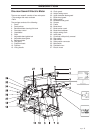
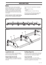
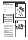
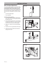
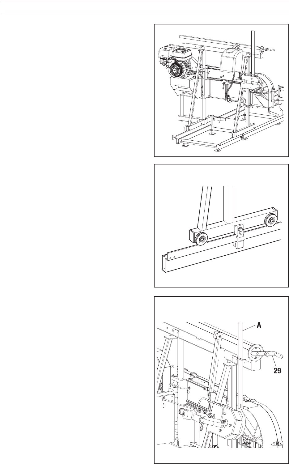
Height Setting (FIG. 4)
The saw unit is secured vertically by two interact-
ing screws. The screws are connected to a chain
for precise and simultaneous movement.
A crank (29) is fitted on the top section of one of
the screws, and is used to set the exact dimen-
sion of the timber thickness. One turn of the
crank moves the bandsaw blade 5 mm. The
height of the bandsaw blade above the rails’
cross members is read on the scale (1).
There are two red markings on the scale that
indicate the lowest saw height with the timber
support raised, one red line for the long timber
support and one red line for the short one.
CAUTION! Sawing under the respective mark-
ings will damage the bandsaw.
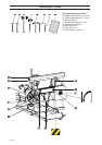
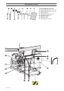
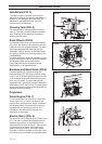
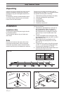
Frame (FIG. 3) and (FIG. 4)
The carriage frame consists of welded square
tubing with requisite corner reinforcement for
stability during cutting.
The frame is equipped with two round runners for
the saw unit's up and down movement. The
guides transfer the saw carriage’s lateral forces
to the frame.
On the underside of the frame are four runners,
fitted with bearings, with slots for securing and
smooth running along the rails.
The carriage is equipped with two adjustable
bearings, which run against the underside of the
rails, to prevent it from lifting.
FIG. 2
FIG. 3
FIG. 4