


English – 21
INSTALLATION
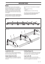
Bandsaw Blade
WARNING!
Wear protective gloves whenever
you handle the bandsaw blade!
On delivery a new bandsaw blade
is rolled up and is in a state of
high mechanical tension. Care-
fully unpack the bandsaw blade
so that it does not fly out and
cause physical injury!
Only bandsaw blades with the part number
531 0194-65 may be used.
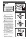
Fit the bandsaw blade as follows:
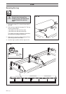
1. Remove the guards over the band wheels.
The guards are attached by three rubber
straps, one upper, one lower, and one in the
middle.
2. Crank the band tension crank (27) anticlock-
wise so that the distance between the band
wheels is as small as possible.
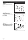
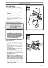
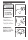
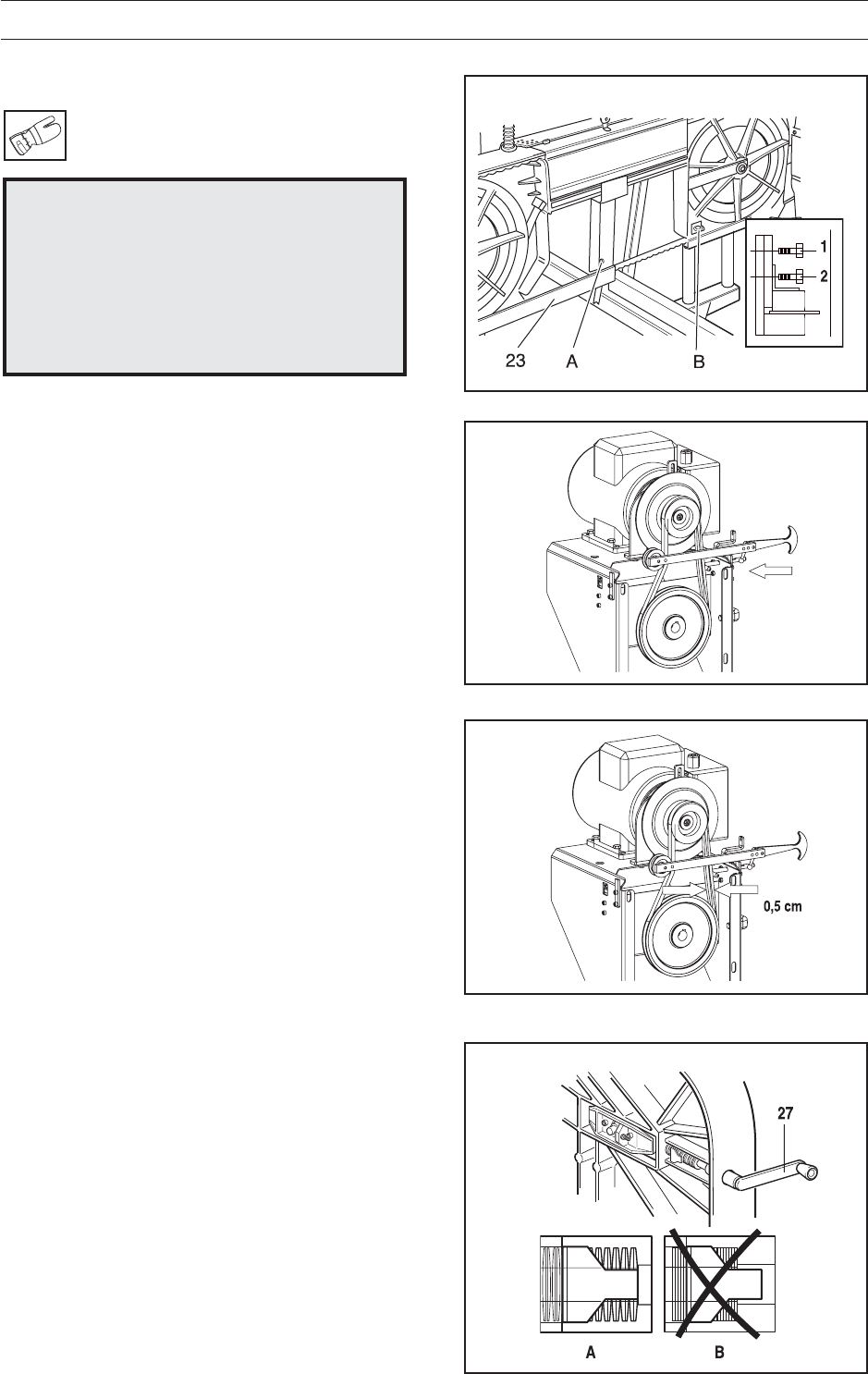
3. Loosen the crank (FIG. 33A), drop the band
guard (23), and attach the bandsaw blade
with the teeth facing. Make sure that the
bandsaw blade enters the adjustable band
guide (8) and the fixed band support (FIG.
33B).
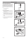
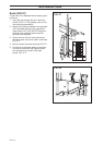
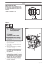
4. Release the belt tensioner by loosening the
belt idler from the engine/motor. See FIG. 34.
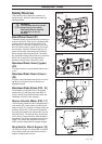
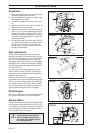
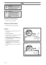
5. Tension the bandsaw blade using the crank
(27) until the spring washers are correctly
compressed. See FIG. 36A. Turn the
bandsaw wheels a few turns by hand, so that
the bandsaw blade centres on the band
wheels. CAUTION! It is important that the
bandsaw blade is not tensioned too much so
that the washers are completely compressed.
See FIG. 36B. The washers should have a
degree of springiness to take up variations in
band tension. Incorrect band tension (too
hard or too loose) means that the bandsaw
blade runs a risk of roaming and coming
loose from the band wheel.
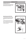
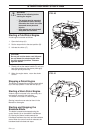
6. Tension the belt FIG. 35 by pulling the han-
dle so that the idler tightens the drive belt.
Lock it. A correctly adjusted belt can be
moved 0.5 cm with one finger.
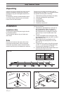
7. Adjust the band guide’s blocks by loosening
the bolts 1 and 2 (FIG. 33). Adjust the blocks
from both directions so that they lie lightly
against the band.
8. Fold up the band guard (23).
9. Position the guards over the band wheels
and secure them with the rubber straps.
Ensure that the safety keys are in the tracks.
!
FIG. 33
FIG. 34
FIG. 35
FIG. 36