24
3
531 03 06-23
Fuel system
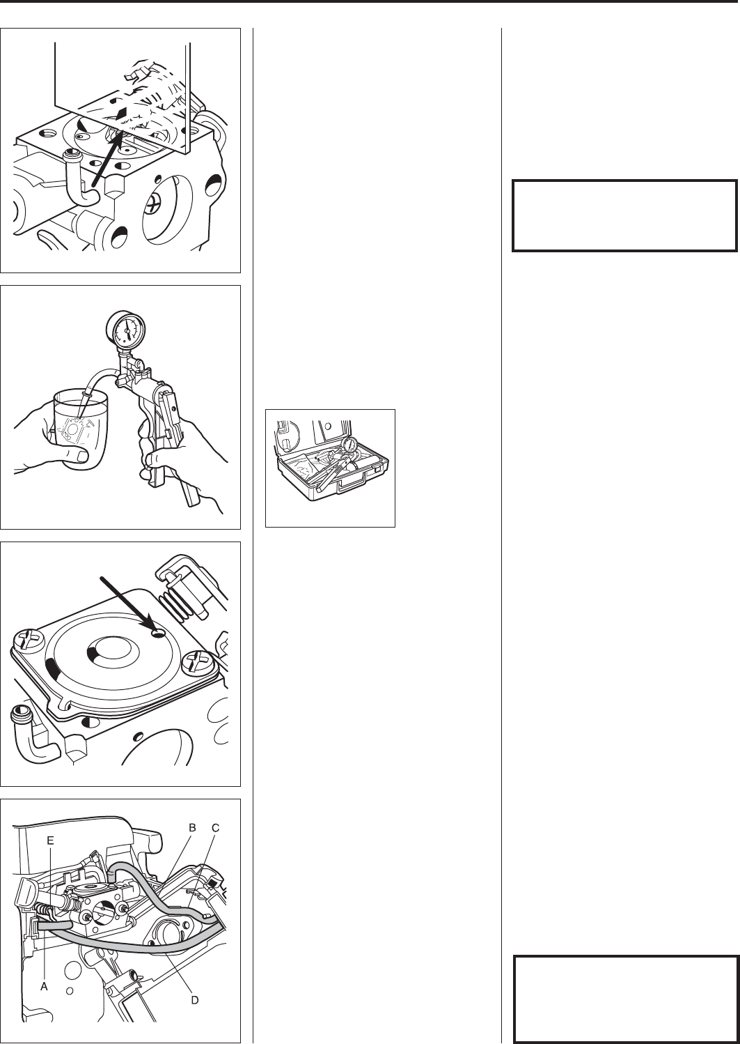
Check that the carburettor is sealed.
No leakage is permitted at 50 kPa.
Connect pressure tester 531 03 06-23
to the fuel intake on the carburettor.
Pump up the pressure to 50 kPa.
Lower the carburettor in a vessel with
petrol in order to discover any leaks
more easily.
No leakage is permitted.
Attach the control diaphragm and
cover.
Place the gasket on the carburettor
housing and then the control dia-
phragm.
Check that the air hole in the cover is
open and screw the cover on.
Assembly
Slide the carburettor into place and
connect the fuel hoses.
Make sure that they do not get pinched.
Connect the throttle cable to the
carburettor.
Assembly
Slide the carburettor into place.
Connect the fuel hose (A) to the carburettor.
Connect the fuel hose (B) to the carburettor
and make sure that it is in the groove (C).
Place the filter holder in place and make
sure that the fuel hose (D) is under the
carburettor and is not pinched.
Connect the throttle cable (E) to the
carburettor.
Screw down the filter holder and attach
the air filter.
Attach the various parts of the measur-
ing unit in the reverse order as set out
for dismantling.
Attach the various parts of the measur-
ing unit in the reverse order as set out
for dismantling.
The lever arm should lie flush with the
carburettor housing.
Too high setting = too much fuel.
Too low setting = too little fuel.
NOTE!
The H-needle is a little shorter
than the L-needle.
NOTE!
Check carefully that the fuel hoses
are not bent or pinched when the
fuel tank is pushed back into
place against the engine body.


