


PRIMUS
R
660 Digital Weather Radar System
A28–1146–111
REV 2 5-7
Radar Facts
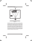
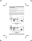
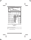
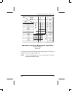
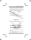
Tables 5–1 and 5–2 give the approximate tilt settings that the ground
targets begin to be displayed on the image periphery for 12– and
18–inch radiators. The range that the ground targets can be observed
is affected by the curvature of the earth, the distance from the aircraft
to the horizon, and altitude above the ground. As the tilt control is
rotated downward, ground targets first appear on the display at less
than maximum range.
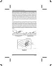
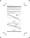
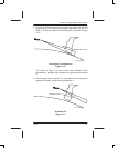
To find the ideal tilt angle after the aircraft is airborne, adjust the TILT
control so that groundclutter does not interfere with viewing of weather
targets. Usually, this can be done by tilting the antenna downward in 1_
increments until ground targets begin to appear at the display periphery.
Ground returns can be distinguished from strong storm cells by
watching for closer ground targets with each small downward increment
of tilt. The more the downward tilt, the closer the ground targets that
are displayed.
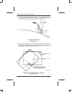
When ground targets are displayed, move the tilt angle upward in 1_
increments until the ground targets begin to disappear. Proper tilt
adjustment is a pilot judgment, but typically the best tilt angle lies where
ground targets are barely visible or just off the radar image.
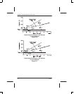
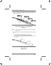
Tables 5–1 and 5–2 give the approximate tilt settings required for
different altitudes and ranges. If the altitude changes or a different
range is selected, adjust the tilt control as required to minimize ground
returns.