


PRIMUS
R
660 Digital Weather Radar System
A28–1146–111
REV 2
Radar Facts
5-56
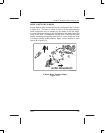
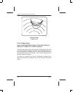
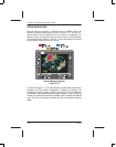
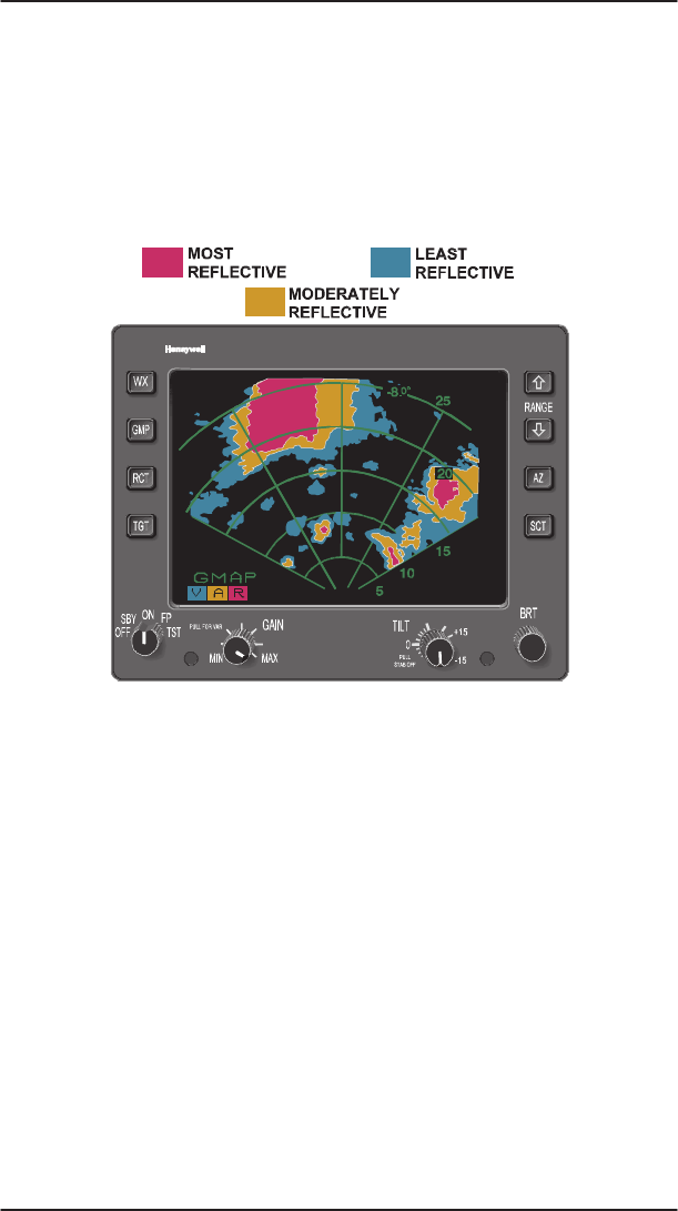
GROUND MAPPING
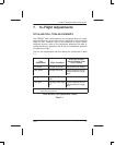
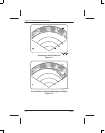
Ground mapping operation is selected with the GMAP button. An
example of ground map display is shown in figure 5–47. Turn the TILT
control down until the desired amount of terrain is displayed. The
degree of down–tilt depends upon the type of terrain, aircraft altitude,
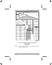
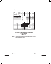
and selected range. Tables 5–10 and 5–11 show tilt settings for maximal
ground target display at selected ranges.
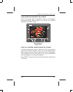
AD–51782–R1@
Ground Mapping Display
Figure 5–47
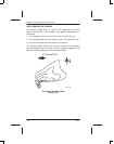
For the low ranges (5, 10, 25, and 50 NM), the transmitter pulsewidth is
narrowed and the receiver bandwidth is widened to enhance the
identification of small targets. In addition, the receiver STC characteristics
are altered to better equalize ground target reflections versus range. As
a result, the preset gain position is generally used to display the desired
map. The pilot can manually decrease the gain to eliminate unwanted
clutter.