


PRIMUS
R
660 Digital Weather Radar System
A28–1146–111
REV 2 4-5
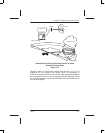
Normal Operation
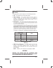
In the absence of intervening targets, the range at which the cyan field
starts is approximately 290 NM with a 12–inch antenna. For the 18–inch
antenna, the cyan field starts beyond 300 NM and therefore is not seen
if there are no intervening targets.
The RCT feature includes attenuation compensation (Refer to Section
5, Radar Facts, for a description of attenuation compensation.). Rainfall
causes attenuation and attenuation compensation modifies the color
calibration to maintain calibration regardless of the amount of
attenuation. Modifying the color calibration results in a change in the
point where calibration can no longer keep the radar system calibrated
for red level targets. The heavier the rainfall, the greater the attenuation
and the shorter the range where extended sensitivity time control
(XSTC) runs out of control. Therefore, the range at which the cyan
background starts varies depending on the amount of attenuation. The
greater the attenuation, the closer the start of the cyan field.
The radar’s calibration includes a nominal allowance for radome losses.
Excessive losses in the radome seriously affect radar calibration. One
possible means of verification are signal returns from known targets.
Honeywell recommends that the pilot report evidence of weak returns
to ensure that radome performance is maintained at a level that does
not affect radar calibration.
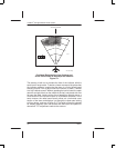
Target alert can be selected in any WX range. The target alert circuit
monitors for hazardous targets within ±7.5_ of the aircraft centerline.
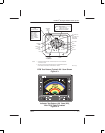
Radar Mode – Ground Mapping
NOTE: Refer to Tilt Management in Section 5, Radar Facts, for
additional information on the use of tilt control.
Ground–mapping operation is selected by setting the controls
to GMAP. The TILT control is turned down until a usable amount of
navigable terrain is displayed. The degree of down–tilt depends on the
aircraft altitude and the selected range.
The receiver sensitivity time control (STC) characteristics are altered
to equalize ground–target reflection versus range. As a result, selecting
preset GAIN generally creates the desired mapping display. However,
the pilot can control the gain manually (by selecting manual gain and
rotating the GAIN control) to help achieve an optimum display.
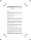
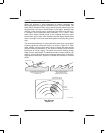
With experience, the pilot can interpret the color display patterns that
indicate water regions, coast lines, hilly or mountainous regions, cities,
or even large structures. A good learning method is to practice
ground–mapping during flights in clear visibility where the radar display
can be visually compared with the terrain.