


PRIMUS
R
660 Digital Weather Radar System
A28–1146–111
REV 2 5-5
Radar Facts
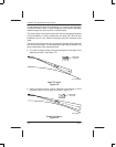
TILT MANAGEMENT
The pilot can use tilt management techniques to minimize ground
clutter when viewing weather targets.
Assume the aircraft is flying over relatively smooth terrain that is
equivalent to sea level in altitude. The pilot must make adjustments for
the effects of mountainous terrain.
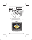
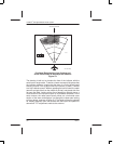
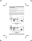
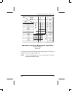
The figures below help to visualize the relationship between tilt angle,
flight altitude, and selected range. Figures 5–4 and 5–5 show the
distance above and below aircraft altitude that is illuminated by the
flat–plate radiator during level flight with 0_ tilt. Figures 5–6 and 5–7
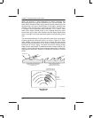
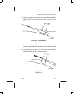
show a representative low altitude situation, with the antenna adjusted
for 2.8_ up–tilt.
ELEVATION IN FEET
80,000
70,000
60,000
50,000
30,000
20,000
10,000
0
0
25 50
RANGE NAUTICAL MILES
100
AD–35693@
CENTER OF RADAR BEAM
20,000 FT
20,000 FT
41,800 FT
41,800 FT
10,500 FT
10,500 FT
7.9
ZERO TILT
Radar Beam Illumination High Altitude
12–Inch Radiator
Figure 5–4
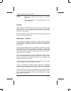
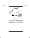
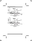
ELEVATION IN FEET
80,000
70,000
60,000
50,000
30,000
20,000
10,000
0
02550
RANGE NAUTICAL MILES
100
AD–17717–R1@
CENTER OF RADAR BEAM
14,800 FT
14,800 FT
29,000 FT
29,000 FT
7,400 FT
7,400 FT
5.6
ZERO TILT
Radar Beam Illumination High Altitude
18–Inch Radiator
Figure 5–5