


9
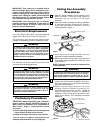
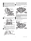
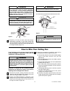
Hanger bracket must seat firmly against outlet box. If
the outlet box is recessed, remove wall board until
bracket contacts box. If bracket and/or outlet box are
not securely attached, the fan could wobble or fall.
WARNING
TWO SCREWS
SUPPLIED WITH
OUTLET BOX
HANGER
BRACKET
TAB
OUTLET
BOX
Figure 21
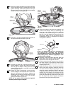
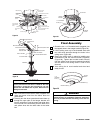
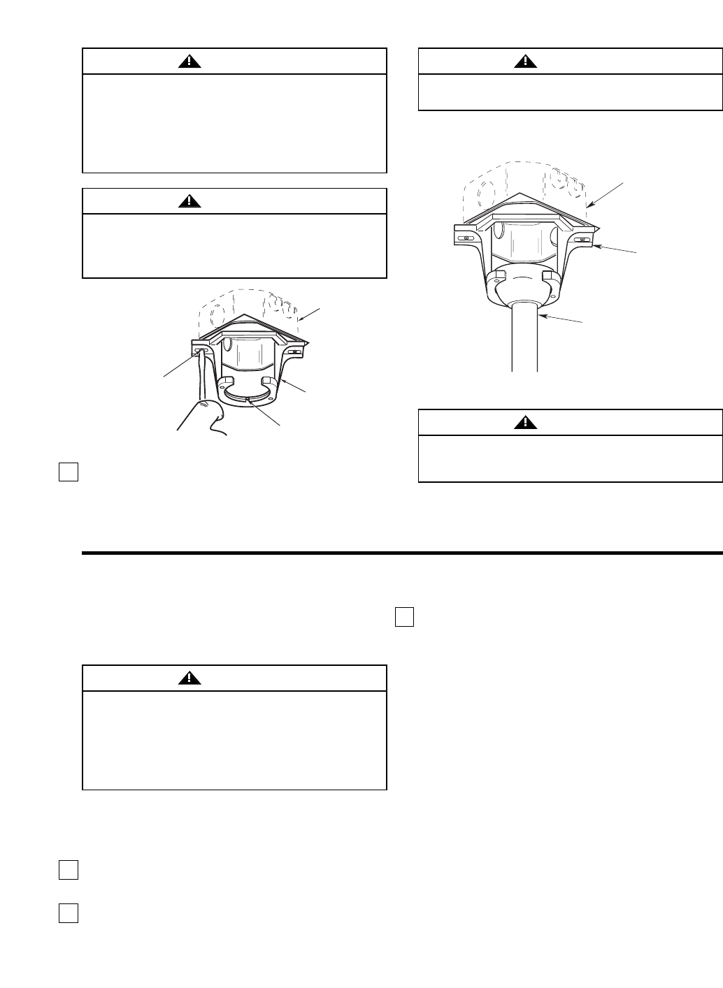
NOTE: CEILING COVER, SUPPLY WIRES AND FAN WIRES OMITTED FOR CLARITY.
OUTLET
BOX
HANGER
BRACKET
HANGER BALL/
DOWNROD ASSEMBLY
Figure 22
To avoid possible fire or shock, do not pinch wires
between the hanger ball/downrod assembly and the
hanger bracket.
WARNING
To reduce the risk of fire, electric shock, or personal
injury, mount fan to outlet box marked “Acceptable
for Fan Support”, and use screws supplied with
outlet box. Most outlet boxes commonly used for
support of light fixtures are not acceptable for fan
support and may need to be replaced. Consult a
qualified electrician if in doubt.
WARNING
2. Carefully lift the fan and seat the hanger
ball/downrod assembly on the hanger bracket that
was just attached to the outlet box (Figure 22). Be
sure the groove in the ball is lined up with tab on
the hanger bracket (Figure 21).
Failure to seat tab in groove could cause damage to
electrical wires and possible shock or fire hazard.
WARNING
Turning off wall switch is not sufficient. To avoid
possible electrical shock, be sure electricity is
turned off at the main fuse or circuit breaker box
before wiring. All wiring must be in accordance with
National and Local codes and the ceiling fan must be
properly grounded as a precaution against possible
electrical shock.
WARNING
If you feel that you do not have enough electrical
wiring knowledge or experience, have your fan
installed by a licensed electrician.
CAUTION: To reduce the risk of electrical shock,
disconnect the electrical supply circuit before
installing the fan and light kit or receiver.
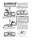
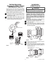
1. Pull the wire leads, coming from the end of the
downrod, and the supply wires through the open
side of the hanger bracket. (Figure 23).
2. Position the SW105 Receiver (supplied) in the
ceiling cover so that the flat side of the receiver
faces up and the open portion of the receiver is to
the right, as shown in Figure 23.
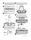
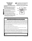
3. Using wire connectors (supplied), make wiring
connections as follows (Figure 23 and 24):
a. Connect the white fan wire and the white supply
wire to the white receiver wire (AC IN/
MOTOR N).
b. Connect the black fan wire to the black receiver
wire (TO MOTOR L).
c. Connect the black supply wire to the black/white
receiver wire (AC IN L).
d. Cut off the ends of the blue and yellow receiver
wires and strip back insulation 1/2-inch from the
ends of the wires.
e. Connect the blue fan wire to the blue receiver
wire (BOTTOM LIGHT).
f. Connect the yellow fan wire to the yellow
receiver wire (UPPER LIGHT).
g. Connect the green ground wires from the
hanger bracket and the hanger ball to the supply
ground wire (bare or green).
How to Wire Your Ceiling Fan
U.L. Model No.: CF3200