


6
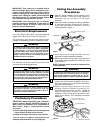
YELLOW
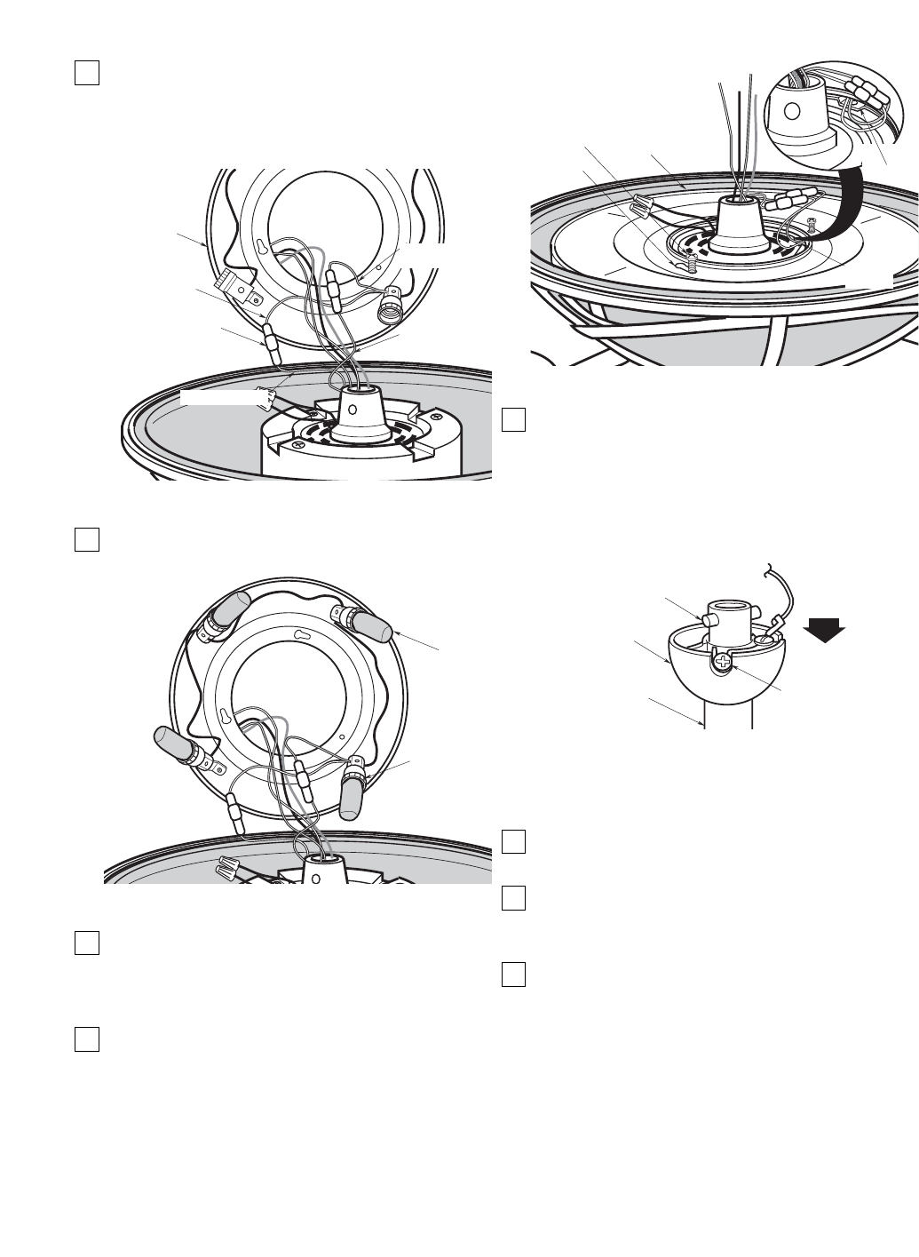
FAN WIRE
ONE-PIN
CONNECTOR
LIGHT KIT
ASSEMBLY
WHITE LIGHT KIT
ASSEMBLY WIRE
WHITE FAN WIRE
YELLOW LIGHT KIT
ASSEMBLY WIRE
Figure 8
15-WATT
CANDELABRA
BASE LIGHT
BULB (4)
LIGHT KIT
ASSEMBLY
SOCKET (4)
Figure 9
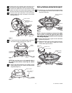
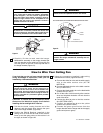
15. Securely connect the white fan one-pin connector
wire to the white one-pin connector wire from the
light kit assembly. Connect the yellow fan one-pin
connector wire to the yellow light kit assembly
one-pin connector wire (Figure 8).
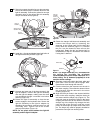
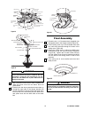
16. Install four 15-watt candelabra base light bulbs in
the light kit assembly sockets (Figure 9).
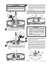
17. Unscrew and save one of the three screws in the
light kit adapter. Position the light kit assembly
onto the light kit adapter, making sure the wires
are positioned through a notched hole before
securing (Figure 10).
18. Rotate the light kit assembly so that the two
screws engage in the keyholes slots. Secure the
light kit assembly to the light kit adapter by
threading the previously removed screw into the
remaining hole. Tighten the three screws
securely at this time. (Figure 10).
NOTE: Do not pinch wires between the light kit
assembly and the light kit adapter.
LIGHT KIT
ASSEMBLY
SCREW (3)
LIGHT KIT
ASSEMBLY
KEYHOLE
SLOTS
NOTCHED
HOLE
NOTCHED
HOLE
Figure 10
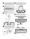
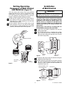
19. Obtain the hanger ball/downrod assembly and
remove the hanger ball by loosening the
setscrew in the hanger ball until the ball falls
freely down the downrod (Figure 11). Remove
the pin from the downrod, then remove the
hanger ball. Retain the pin and hanger ball for
reinstallation in Step 27. Discard the 12” downrod
if using the 6” downrod.
NOTE: The longer downrod (12”) furnished with
the ceiling fan provides the minimum
recommended floor-to-fan blade clearance for a
9-foot ceiling. The 6” downrod (supplied) is to be
used for shorter ceilings.
20. Separate, untwist and unkink the black, white and
blue motor wires and the yellow uplight lead.
Route these wires through the downrod.
21. Fold the wires from the downrod into the slot in
the motor coupling. Then slide the downrod down
the wires and seat the downrod in the motor
coupling (Figure 12).
22. Align the clevis pin holes in the downrod with the
holes in the motor coupling. Install the clevis pin
and secure with the hairpin clip (Figure 12). The
clevis pin must go through the holes in the motor
coupling and the holes in the downrod. Push the
straight leg of the hairpin clip through the hole
near the end of the clevis pin until the curved
portion of the hairpin clip snaps around the clevis
pin. The hairpin clip must be properly installed to
prevent the clevis pin from working loose.
HANGER BALL
PIN
DOWNROD
SETSCREW
Figure 11
U.L. Model No.: CF3200U.L. Model No.: CF3200