


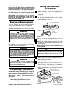
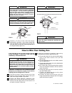

7. Remove the wire connector from the white wire of
the switch housing plate. Retain for the next step.
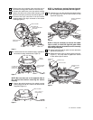
8. Connect the white wire from the switch housing
plate to the white wire of the switch housing, using
the wire connector previously removed (Figure 3).
9. Connect the 9-pin connector from the switch
housing plate to the 9-pin connector of the switch
housing (Figure 3).
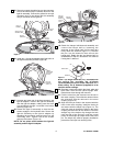
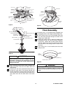
10. Tuck all wires into the switch housing, opposite of
the switch housing notched hole (Figure 4).
NOTE: Be sure wires are on the opposite side of
the notched hole before securing the switch
housing.
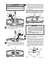
11. Secure the switch housing to the switch housing
plate using three #8-32 x 10mm flat head screws
(supplied) (Figure 5).
5
SWITCH HOUSING
9-PIN CONNECTOR
WIRE CONNECTOR
SWITCH HOUSING PLATE
WHITE WIRE
SWITCH HOUSING
WHITE WIRE
Figure 3
ALL WIRES AND
CONNECTORS
LOCATION
SWITCH HOUSING
PLATE NOTCHED
HOLE
SWITCH
HOUSING
Figure 4
#8-32 x 10mm FLAT
HEAD SCREW (3)
SWITCH HOUSING
Figure 5
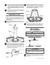
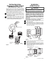
PARTIALLY ASSEMBLED
CEILING FAN
STYROFOAM
Figure 6
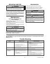
DECORATIVE LIGHT
KIT RING
LIGHT KIT
GLASS
LIGHT KIT GLASS
RUBBER CLIP (3)
RUBBER CLIP
SCREW
Figure 7
12. Carefully turn over the partially assembled ceiling
fan and place the onto the flat surface of the
styrofoam (Figure 6).
13. Gently place the light kit glass into the decorative
light kit ring (Figure 7).
14. Rotate the rubber clips to secure glass into place.
(Figure 7). You may need to tighten the screws
on the rubber clips to secure.
U.L. Model No.: CF3200
NOTE: If installing an optional Emerson light kit,
follow the instructions provided with the light kit.
NOTE: It may be necessary to remove the rubber
clips in order to install the light kit glass. Make
sure rubber clips are reinstalled so as to securely
hold the light kit glass.