


8
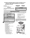
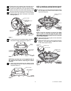
28. The blue, black, white, and yellow leads exiting
the downrod are 80-inches long. Before installing
the fan, measure up approximately 6 to 9-inches
above the ball/downrod assembly. Cut off excess
leads and strip back insulation 1/2-inch from end
of leads.
29. You have now completed the initial assembly of
your new ceiling fan. You can now proceed with
hanging and wiring your fan.
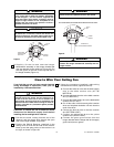
Installation of the
Decorative Scroll Assembly
NOTE: The following procedures are to be
performed only if you have installed the 12” or
longer downrod.
1. Slide the decorative downrod cover over the 12”
downrod to rest upon the motor coupling cover
(Figure 17).
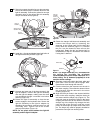
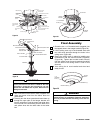
2. Remove the four screws in the scroll collar and
save for the following procedure. Assemble the
decorative scroll assembly to the scroll collar using
the previously removed screw (Figure 18).
Assemble the remaining three decorative scroll
assemblies in the same manner.
DECORATIVE
DOWNROD
COVER
12" DOWNROD
OR LONGER
MOTOR
COUPLING
COVER
Figure 17
SCROLL COLLAR
DECORATIVE SCROLL
ASSEMBLY (4)
SCROLL COLLAR SCREWS (4)
Figure 18
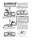
3. Slide the assembled decorative scroll over the 12”
downrod and position each scroll leg on the
decorative light kit ring (Figure 19). Secure each of
the four decorative scroll legs using four #8-32 x
15mm flat head screws (supplied).
ASSEMBLED
DECORATIVE SCROLL
#8-32 x 15mm FLAT
HEAD SCREW (1 per
leg)
DECORATIVE
LIGHT KIT RING
Figure 19
4. You have now completed the installation of the
decorative scroll assembly. Proceed to Page 7,
Step 27 to complete your ceiling fan installation.
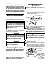
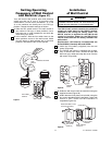
The outlet box and joist must be securely mounted
and capable of supporting at least 50 lbs. Use only a
U.L. outlet box listed as “Acceptable for Fan
Support”.
WARNING
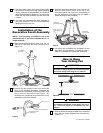
How to Hang
Your Ceiling Fan
FLOOR
CEILING
AT LEAST
7'
Figure 20
The fan must be hung with at least 7' of clearance
from floor to blades (Figure 20). Do NOT hang this
fan on an 8’ ceiling when using the 12” downrod.
WARNING
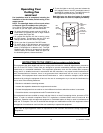
1. Securely attach the hanger bracket to the outlet box
using the two screws supplied with the outlet box.
(Figure 21.)
U.L. Model No.: CF3200