


3
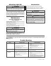
This Manual Is Designed to Make it as Easy as Possible for You to
Assemble, Install, Operate and Maintain Your Ceiling Fan
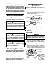
One stepladder
One wire stripper
One Phillips head screwdriver
Four 15-watt (max.) candelabra base bulbs
MATERIALS
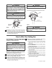
Wiring outlet box and box connectors must be of type
required by the local code. The minimum wire would
be a 3-conductor (2-wire with ground) of the wire
size, to right:
Installed Wire Length Wire Size A.W.G.
Up to 50 ft. 14
50-100 ft. 12
If you feel you do not have enough wiring knowledge or
experience, have your fan installed by a licensed
electrician.
WARNING
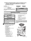
Unpacking Instructions
For your convenience, check-off boxes are provided next to each step. As each step is completed, place
a check mark in the box. This will insure that all steps have been completed and will be helpful in finding
your place should you be interrupted.
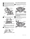
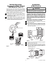
BLADE
10-32 x 10mm PAN HEAD SCREW
(4 Per Blade)
FLANGE
ASSEMBLY
FLANGE
MEDALLION
BLADE
10-32 x 10mm PAN HEAD SCREW
(4 Per Blade)
FLANGE
ASSEMBLY
FLANGE
MEDALLION
BLADE
10-32 x 10mm PAN HEAD SCREW
(4 Per Blade)
FLANGE
ASSEMBLY
FLANGE
MEDALLION
BLADE
10-32 x 10mm PAN HEAD SCREW
(4 Per Blade)
FLANGE
ASSEMBLY
FLANGE
MEDALLION
BLADE
10-32 x 10mm PAN HEAD SCREW
(4 Per Blade)
FLANGE
ASSEMBLY
FLANGE
MEDALLION
h.
m.
p.
H
I
H
I
M
E
D
M
E
D
L
O
W
L
O
W
F
A
N
O
F
F
R
E
V
R
E
V
L
I
G
H
T
q.
r.
o.
n.
l.
k.
j.
g.
i.
d.
f.
e.
a.
c.
b.
Do not install or use fan if any part is damaged or
missing. Call Toll-Free:
1-800-654-3545
This product is designed to use only those parts
supplied with this product and/or any accessories
designated specifically for use with this product by
Emerson Electric Co. Substitution of parts or
accessories not designated for use with this product
by Emerson Electric Co. could result in personal
injury or property damage.
WARNING
WARNING
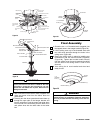
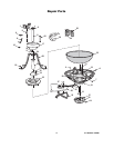
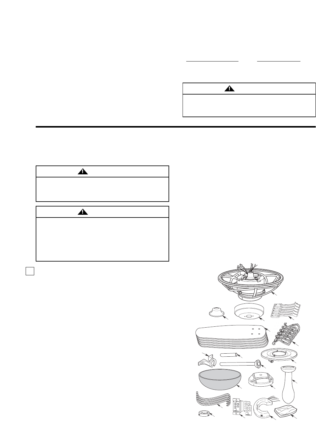
1. Open styrofoam unit containing fan. Remove upper
and center sections of styrofoam unit. Remove parts
and check to see that you have received the following:
a. One Fan Motor and Housing Assembly
b. One Motor Coupling Cover
c. One Ceiling Cover
d. Five Fan Blades
e. Five Flanges
f. Five Flange Medallions
g. One Hanger Ball/12” Downrod Assembly
h. One Hanger Bracket
i. One 6” Downrod
j. One Light Kit Assembly
k. One Light Kit Glass
l. One Switch Housing
m. One Decorative Downrod Cover
n. Four Decorative Scrolls
o. One Scroll Collar
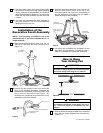
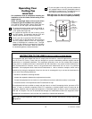
p. One SW116 Fan/Light Wall Control
(transmitter) Includes Three Covers
q. One SW105 Receiver
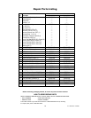
r. One Loose Parts Bag Containing:
1. One 5/16-18 x 1/4” setscrew
2. One 5/32" hex wrench
3. Four 8-32 x 1-1/4” threaded studs
4. Four #8-32 knurled knobs
Tools Needed for Assembly
5. Four #8 external tooth lockwashers
6. Five 12 Ga. wire connectors
7. One hairpin clip
8. One clevis pin
9. Twenty-one 10-32 x 10mm pan head
screws
10. Eleven #8-32 x 14mm oval head screws
11. Four #8-32 x 10mm flat head screws
12. Five #8-32 x 15mm flat head screws
13. One balancing kit
NOTE: Place the parts from the loose parts bags
in small containers to keep them from being lost.
If any parts are missing, contact your local
retailer or catalog outlet for replacement before
proceeding.
U.L. Model No.: CF3200