


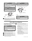
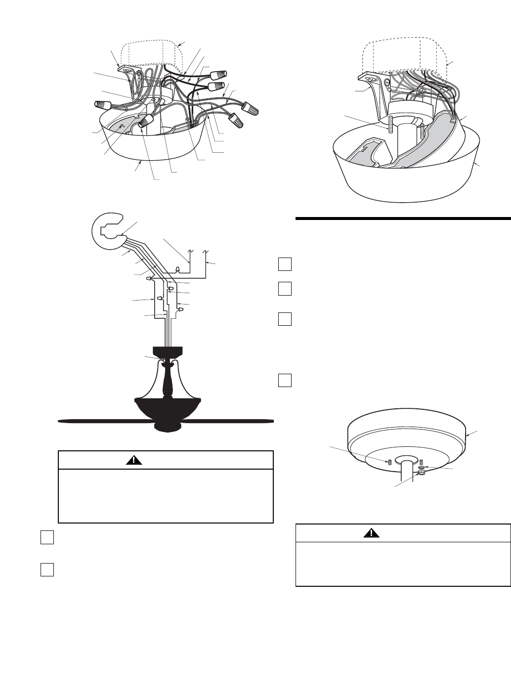
1-1/4"
THREADED
STUD (2)
CEILING
COVER
KNURLED KNOB (2)
LOCKWASHER (2)
1-1/4" THREADED
STUDS (2)
HANGER
BRACKET
OUTLET BOX
RECEIVER
CEILING
COVER
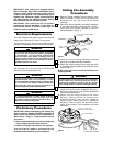
Figure 25
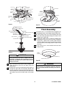
WHITE SUPPLY WIRE
BLACK FAN WIRE
SW105 RECEIVER
WHITE FAN WIRE
BLUE RECEIVER WIRE
BLUE FAN WIRE
BLACK SUPPLY
WIRE
WHITE RECEIVER WIRE
BLACK RECEIVER WIRE
BLACK/WHITE
RECEIVER WIRE
YELLOW RECEIVER WIRE
DOWNROD
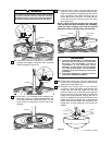
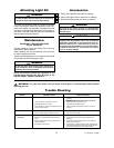
Check to see that all connections are tight, including
ground, and that no bare wire is visible at the wire
connectors, except for the ground wire. Do not
operate fan until blades are in place. Noise and fan
damage could result.
WARNING
4. After connections have been made, separate the
white and green wires from the black, blue and
yellow wires.
5. Carefully turn the wires upward and insert them up
through the open side of the hanger bracket and
into the outlet box. Push the green and white wires
into one side of the outlet box; push the black, blue
and yellow wires into the other side of the outlet
box.
Figure 24
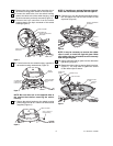
Final Assembly
1. Screw the two 1-1/4” threaded studs (supplied) into
the tapped holes in the hanger bracket (Figure 25).
2. Lift the ceiling cover up to the threaded studs and
turn until studs protrude through the holes in the
ceiling cover (Figure 26).
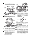
3. Secure the ceiling cover in place by installing two
lockwashers and two knurled knobs (supplied)
(Figure 26). Tighten the knurled knobs securely
until the ceiling cover fits snugly against the ceiling
and the hole in the ceiling cover is clear of the
downrod.
4. Your ceiling fan in now installed and wired and
ready for use.
Figure 26
To avoid possible fire or shock, make sure that the
electrical wires are completely inside the outlet box
and not pinched between the ceiling cover and the
ceiling.
WARNING
OUTLET BOX
BLACK SUPPLY WIRE
BLACK/WHITE RECEIVER WIRE
BLACK FAN WIRE
BLUE FAN WIRE
BLUE RECEIVER
WIRE
YELLOW FAN WIRE
YELLOW RECEIVER WIRE
CEILING COVER
WHITE RECEIVER WIRE
WHITE FAN WIRE
WIRE CONNECTOR
RECEIVER
WHITE SUPPLY
WIRE
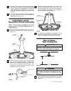
SUPPLY GROUND
WIRE (GREEN OR
BARE)
HANGER BALL
GROUND WIRE
(GREEN)
HANGER BRACKET
GROUND WIRE
(GREEN)
HANGER BRACKET
BLACK RECEIVER WIRE
OPEN
PORTION OF
RECEIVER
HERE
10
Figure 23
U.L. Model No.: CF3200U.L. Model No.: CF3200