


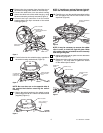
The SW116 wall control transmits the command
signals via radio waves to the SW105 receiver
installed in the ceiling fan ceiling cover. The
SW105 receiver is required for the SW116 wall
control to function. Power for the SW116 wall
control comes from the 12V battery, located in the
wall control.
Replacement 12V batteries recommended are
Duracell MN21, Eveready A23, and GP23A.
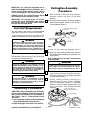
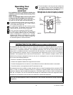
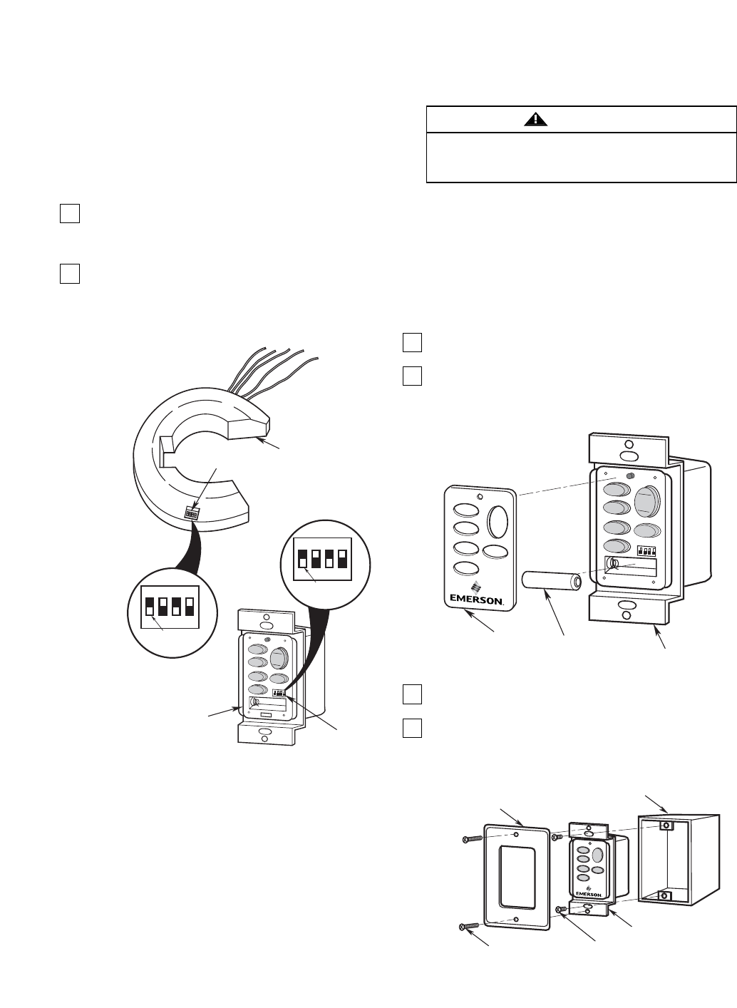
1. Install the 12V battery (supplied) into the wall
control (Figure 28).
2. The SW116 wall control is supplied with a white,
ivory or almond color cover. Choose the style that
best suits your needs and snap the cover onto the
wall control (Figure 28).
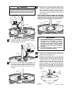
3. Install the wall control onto the outlet box using the
supplied screws (Figure 29).
4. Install decorator wall plate (not included) using the
two screws provided with the wall plate. Leave wall
control in “OFF” mode until fan installation is
completed (Figure 29).
12V BATTERY
WALL
CONTROL
COVER
SW116 WALL
CONTROL
HI
HI
MED
M
ED
LOW
LOW
FAN OFF
REV
REV
L
IG
H
T
D
/L
U
/L
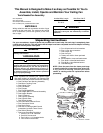
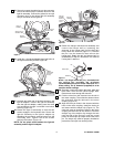
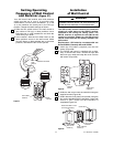
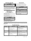
Setting Operating
Frequency of Wall Control
and Receiver
(Figure 27)
Your wall control and receiver have code switches
which must be set in one of 16 possible code
combinations. The four levers (numbered 1, 2, 3, and
4) on the switches are factory-set in the ON (up)
position. Change the switch settings as follows:
1. Slide the four switch levers in the wall control to
your choice of ON (up) or down positions. Use a
ball-point pen or small screwdriver and slide the
levers firmly up or down.
2. In the receiver, slide the four switch levers to the
same positions as set in the wall control. Make
sure the levers on both switches are in the same
positions, otherwise the fan will not operate.
ON
1
234
RECEIVER SWITCH
LEVERS
ON
1
234
WALL CONTROL
LEVERS
CODE
SWITCH
SW105 RECEIVER
CODE
SWITCH
SW116 WALL
CONTROL
H
I
H
I
M
E
D
M
E
D
L
O
W
L
O
W
FA
N
O
F
F
R
E
V
R
E
V
L
IG
H
T
Figure 27
Figure 28
SW116 WALL
CONTROL
DECORATIVE WALL PLATE
(Purchased Separately)
OUTLET BOX
WALL PLATE
SCREW (2)
WALL CONTROL
SCREW (2)
REV
HI
MED
LOW
FA
N
O
F
F
U
/L
D
/L
L
IG
H
T
Figure 29
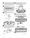
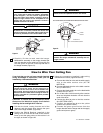
Turning off wall switch is not sufficient. To avoid
possible electrical shock, be sure electricity is
turned off at the main fuse or circuit breaker box.
WARNING
Installation
of Wall Control
11
U.L. Model No.: CF3200