


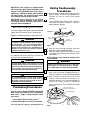
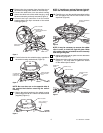
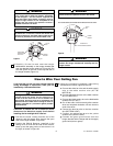
1. Place the flange assembly onto the bottom of the
blade assembly. Place the flange medallion
assembly into the four holes of the blade
assembly.
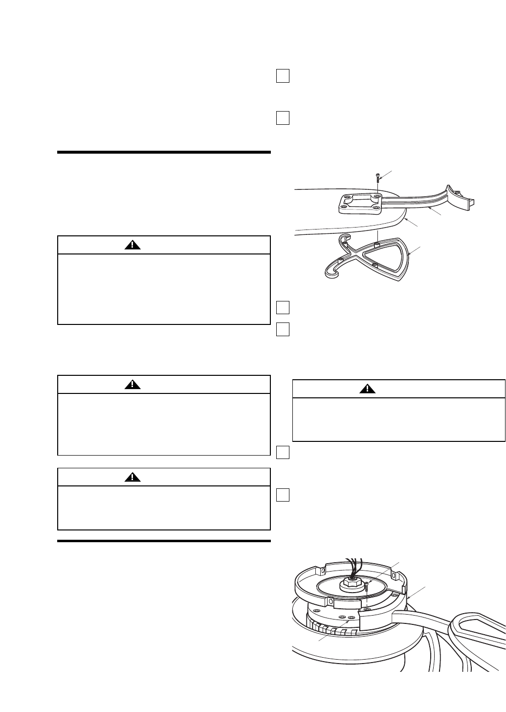
2. Secure the flange assembly and flange medallion
to the blade assembly using the four #10-32 x
10mm pan head screws. Repeat for the four
remaining blades. (Figure 1)
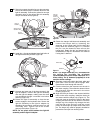
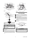
3. Place the motor housing assembly onto the
styrofoam for blade assembly installation.
4. Rotate the switch housing plate to align the holes
in the blade flange assembly with the holes in the
motor housing.
NOTE: Take care not to scratch fan housing when
installing blades.
5. Attach the flange assembly using two #8-32 x
14mm oval head screws (supplied) (Figure 2).
Install the remaining four fan blades assemblies
using the same procedure.
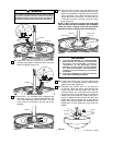
6. Gently snug all flange screws to the motor
housing, working around the housing in a
clockwise sequence. Next, securely tighten all
flange screws, again working in a clockwise
sequence. Failure to follow this procedure could
result in fan wobble. This completes the blade
installation.
BLADE
10-32 x 10mm PAN HEAD SCREW
(4 Per Blade)
FLANGE
ASSEMBLY
FLANGE
MEDALLION
Figure 1
#8-32 x 14mm OVAL HEAD
SCREW (2 Per Flange Assembly)
FLANGE ASSEMBLY
MOTOR
HOUSING
Figure 2
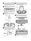
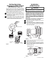
If your fan is to replace an existing ceiling light fixture,
turn electricity off at the main fuse box at this time
and remove the existing light fixture.
Turning off wall switch is not sufficient. To avoid
possible electrical shock, be sure electricity is turned
off at the main fuse box before wiring. All wiring must
be in accordance with national and local codes and
the ceiling fan must be properly grounded as a
precaution against possible electrical shock.
WARNING
Your new ceiling fan will require a grounded electrical
supply line of 120 volts AC, 60 Hz, 15 amp circuit.
The outlet box must be securely anchored and
capable of withstanding a load of at least 50 pounds.
To reduce the risk of fire, electric shock, or personal
injury, mount fan to outlet box marked “Acceptable
for Fan Support”, and use screws supplied with
outlet box. Most outlet boxes commonly used for
support of light fixtures are not acceptable for fan
support and may need to be replaced. Consult a
qualified electrician if in doubt.
WARNING
Electrical Requirements
Ceiling Fan Assembly
Procedures
To avoid possible fire or shock, follow all wiring
instructions carefully. Any electrical work not
described in these instructions should be done or
approved by a licensed electrician.
WARNING
4
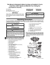
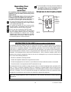
IMPORTANT: Your ceiling fan is supplied with an
SW116 Fan/Light Wall Control (transmitter) and a
remote control SW105 Receiver which mounts
under the ceiling cover. This system allows you to
regulate your ceiling fan speed, airflow direction,
and light intensity. An optional Emerson Electric
SR110 Remote Control may also be used.
IMPORTANT: Your ceiling fan will not function
properly and may be damaged, if used with any
wall dimmer switch or control other than the
Emerson controls listed above.
Preliminary Procedures
IMPORTANT: Before assembling your ceiling fan,
refer to sections “Setting Operating Frequency of
Wall Control and Receiver” and “Installation of
Wall Control”, Page 11. These sections instruct
you how to:
a. Set the operating frequency of the fan/light wall
control and the remote control receiver.
b. Install the fan/light wall control in the wall box.
You will then be ready to proceed with the
assembly and installation of your ceiling fan.
To reduce the risk of personal injury, do not bend the
blade flange when installing the blade flanges,
balancing the blades or cleaning the fan. Do not
insert foreign objects in between rotating fan blades.
WARNING
U.L. Model No.: CF3200