


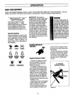

ASSEMBLY
Read these instructions in their en-
tirety before you attempt to assem-
ble or operate your new equipment.
Your new equipment has been as-
sembled at the factory with the ex-
ception of those parts left unassem-
bled for shipping purposes. To en-
sure safe and proper operation of
your machine, all parts and hard-
ware you install or adjust must be
tightened according to the assem-
bly instructions. Use the correct
tools as necessary to ensure proper
tightness..
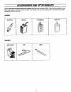
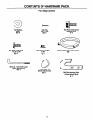
ToolsNeededForAssembly:
• (1) 7/16" Wrench
• (1) 3/8" Wrench
• (2) 1/2" Wrenches
• (1) Needle-nose Pliers
• (1) Wire Cutter Pliers
• (1) Tire.Gauge
• (1) Scissors or Pen Knife
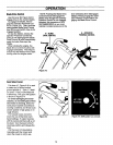
UNPACKING
INSTRUCTIONS
• Inspect your machine immediate-
ly. Be sure neither the carton nor
contents have been damaged. If
you find or have reason to sus-
pect damage, contact your near-
est Sears Service Center/Depart-
ment for assistance.
• Cut plastic banding with scissors.
Open box flaps and remove any
packing material from around the
machine. Remove any staples
securing bottom of carton to wood
pallet. Lift off carton. Cut metal
straps secudng unit to base.
Leave unit on base of pallet dur-
ing assembly steps (to safely re-
move unitfrom base, wait until
you have completed assembly
steps 1-2). Before disposing of
the carton or any of the packing
materials, be sure to check them
thoroughly for any small parts.
• Cut plastic tie straps holding three
long control rods to handlebars.
Also remove any packaging
around the handlebars.
• Perform the assembly on a clean,
level surface. If you need to
move the machine, be careful not
to severely bend any of the con-
trol cables on the equipment.
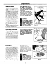
ASSEMBLYSTEPS
Before starting any assembly
steps, disconnect the engine
spark plug wire from the spark
plug.
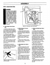
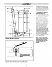
STEP1: AttachHandlebars
• If applicable, cutand remove any
plastic ties holding wheel drive rod
(F, Figure 2-5) to left handlebar and
blade ddve rod (C, Figure 2-5) to
right handlebar. Put rods aside.
• Handlebars (A, Figure 2-2) are
shipped partially assembled with two
screws (Y, Figure2-2) loosely in-
stalled. It may be necessary to
loosen screws (Y) further to allow the
handlebars to clear the engine air
cleaner.
• Rotate handlebars over engine
and position as shown in Figure 2-2.
Be careful that the handlebars clear
the unit while unfolding. Also, put
end of control rod (E, Figures 2-3
and 2-5) into cut-out (W, Figures
2-2 and 2-3) in back of frame while
rotating handlebars into position.
• Install two 5/16"-18 x 3/4" hex
flange screws (B, Figure 2-2).
• Tighten all four screws (B and Y).
• Secure the engine throttle cable
to the left handlebar with a cable tie
from the hardware bag. Clip off any
excess tie length.
, B Y ,
Figure 2-2: Attach handlebars.
9