


SERVICE AND ADJUSTMENTS
SPARKPLUG
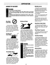
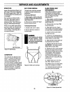
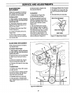
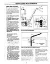
Inspect the spark plug (Figure 5-4)
after every 100 hours of operation.
Be sure the gap is set at .030". Do
not reuse plug if it is severely worn
or damaged.
Best results are obtained with a
new plug. See engine owner's
manual to determine proper re-
placement plug. Use of incorrect
plug can cause engine damage.
NOTE: Do not clean spark plug in
machines which use abrasive grit.
Clean spark plug by scraping or
wire brushing, or washing with a
commercial solvent.
.030"FeelerGauge
Figure 5.4: Spark plug.
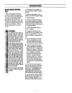
CARBURETOR
The carburetor is adjusted at the
factory. It should not need to be
reset. If black exhaust is noted,
check the air cleaner first. An
over-rich mixture is usually caused
by a poorly serviced or clogged air
cleaner element, not an improperly
adjusted carburetor. If readjust-
ment is necessary, contact your
Sears Service Center.
BELTCOVERREMOVAL
The belt cover must be removed
to perform several maintenance
procedures.
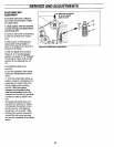
To Remove Belt Cover
1. Stop engine, wait for all parts
to stop moving, and disconnect
spark plug wire.
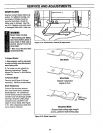
2. Remove four screws (R, Figure
5-5) and remove cover.
To Reinstall Belt Cover
1. Position belt cover in place.
2. Secure with four screws re-
moved earlier.
i WARNING
Oo not operate unit without
belt cover installed. Failure
to follow this instruction
couldresult in personalinjury
orpropertydamage.
Figure 5-5: Belt cover removal
BLADESPINDLEBELT
REPLACEMENT
Follow this procedure to remove
and replace the blade spindle
drive belt (remove blade drive belt
first; see "Blade Drive Belt
Replacement").
1. Stop engine, wait for all parts
to stop moving and disconnect
spark plug wire.
2. Remove belt cover (see "Belt
Cover Removar_.
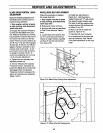
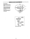
3. Align sight holes (O, Figure
5-6) in pulley with spindle housing-
to-mower deck mounting bolts (L).
4. Loosen screw (J) and rotate
arm (K) tothe rear.
5. Loosen four mounting bolts (L)
securing spindle housing (beneath
mower deck) to mower deck.
6. Slide spindle housing (with pul-
ley attached) toward center.
7. Replace belt (N) with new belt.
.IMPORTANT: Set blades perpen-
dicular (90°) to each other.
8. Rotate arm (K) to move spindle
housing and apply tension to belt.
Belt cogs and pulley groovesmust
mesh together. When applying
moderate finger tension (8-12
Ibs.), belt should deflect approxi-
mately 1/2" (12.7 mm) at (P), mid-
point of deck.
9. Tighten bolts (L) to 15 ft.-Ibs.
(20.3 Nm). Tighten screw (J).
10. Blades must not contact deck.
Check and readjust as needed.
11. Reinstall blade drive belt and
belt cover, removed earlier).
t
• p_0k.T
" _":::-"::!' L ./
.Figure 5-6: Blade Spindle Bell
26