


' SERVICE AND ADJUSTMENTS
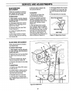
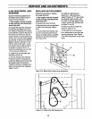
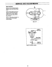
BLADEDRIVECONTROLLEVER
ADJUSTMENT
Make th_ following adjustment if
the Blade Ddve Control lever re-
leases dudng operation. _
1. Stop engine, wait for all parts
to stop moving, and disconnect
spark plug wire.
2. Engage the Operator Presence
Control and the Blade Drive Con-
trol. Without releasing the controls,
look inside the cutout at the roar of
the frame and make sure the Op-
erator Presence Control latches (A
and B, Fig. 5-10) are fully engaged
at point (C). If they are not fully en-
gaged, improper operation or pre-
mature wear could result. To ad-
just, loosen hex nut (D) and short-
en length of control rod (E). To
avoid over-adjusting, turn rod only
1 to 2 turns per adjustment.
3. Tighten hex nut securely after
adjusting control rod.
4. Test by releasing the Operator
Presence Control. If properly ad-
justed, the Blade Drive Control will
disengage when the Operator
Presence Control is released. Re-
adjust as necessary by repeating
Steps 2 and 3.
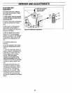
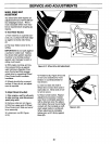
WHEELDRIVEBELTREPLACEMENT
Follow this procedure to replace
the wheel ddve belt.
1. Stop engine, wait for all parts
to stop moving, and disconnect
spark plug wire.
2. Release all mower controls.
3. Remove belt cover as described
in "Belt Cover Removal" instruc-
tions.
4. Locate wheel drive belt (O, Fig-
ure 5-11) and remove it from top
sheave of engine sheave, backsid-
ed idlers (P and Q) and transmis-
sion sheave (R).
5. Install new belt shown in
Figure 5-11. Belt must be in-
stalled "inside out"'V' side of belt
lies against engine sheave only.
Rat side of belt lies against trans-
mission sheave (R) and back-sid-
ed idlers (P and Q).
6. Make sure belt is inside belt
guide (S, Figure 5-11).
7. Reinstall belt cover securely.
8. An adjustment to the drive belt
may be necessary. See "Wheel
Drive Belt Adjustment" on the next
page.
C
E A
-- B
Figure 5-10: Blade Drive Control Lever adjustmenL
I
I
I
I
!
I
!
_Lr!-- -s I
I
I
!
a -I1
Figure 5-11: Wheel drive bolt _placemenL
I
I
I
29