


ASSEMBLY
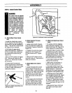
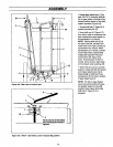
Figure 2-5: Rear view of control rods.
0 M
D
P
Pin(K) must be in this detent
whentransmissionneutral is _
adjusted.
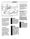
• Rotate gear select lever (I, Fig-
ures 2-6 & 2-7) clockwise until pin
(K) on gear select rod stops in the
neutral position detent on the shift
pattern quadrant (Figure 2-6).
• Thread shift link (P, Figure 2-7)
partially into ball-joint (Y).
• Move shift arm (X, Figure 2-7)
from side to side as necessary into
each transmission gear detent un-
tiltransmission is in neutral.
NOTE: Moving shift arm (X) all
the way to the left, and then one
notch back to the right, should put
transmission into neutral. When :
transmission is in neutral, unit will
move freely when pushed while
holding the Operator Presence
Control lever (W, Figure 2-5)
down. Iftransmission is NOT in
neutral, there willbe a slight drag
on the wheels when pushingunit.
• When shift arm (X) is in neutral
position, rotate shift link (P) toward
end of gear select lever rod (I).
Adjust length of shift link (P) as
necessary to fit into hole in bottom
of gear select lever (I).
NOTE: Pin (K) on Gear Select
Lever (I) must be held in the neu-
tral positiondetent on the shift
quadrant (see Figure 2-6) while
shift link (P, Figure 2-7) is
adjusted.
Figure 2-6: Detail - Gear Select Lever in Neutral (N) position.
11