


ASSEMBLY
STEP2: Attach ControlRods
WARNING
The control rodsare adjusted
at the factory and should not
require additional adjustment
during assembly. After as-
sembling unit, controlrodad-
justment should be checked
(and re-adjusted, if neces-
sary) accordingto information
in "Customer Responsibili-
ties" Section. Severe person-
a] injury or property
damage could result from
not following this
instruction.
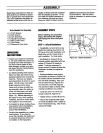
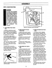
A. AttachWheel DriveControl
Rod
• Locate the wheel drive control
rod (F, Figures 2-3 & 2-5) that you
removed from the left handlebar in
Step 1. This rod has a swivel block
(H, Figure 2-3) on one end.
• At left side of engine frame,
insert swivel block (H, Figures 2-3
& 2-5) on wheel drive control rod
into wheel drive control arm (U,
Figure 2-3).
• Add one 5/16" washer (A, Figure
2-3). Secure with cotter pin (B,
Figure 2-3). Bend ends of cotter
pin to secure.
• At upper end of control rod,
secure angled end to Wheel Drive
Control lever (V, Figure 2-4), using
a cotter pin (BB). Bend ends of
cotter pin to secure.
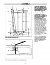
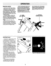
B
V
Figure 2-4: Attach wheel drive con-
trol rod to lever.
AB
Figure 2-3: Left-hand control rods detail.
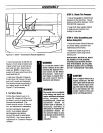
B. AttachOperatorPresence
ControlRod:
• Locate control rod (E, Figures.
2-3 & 2-5) attached at upper end
to Operator Presence Control (W,
Figure 2-5).
• At bottom of control rod, insert
swivel block (G, Figures 2-3 &
2-5) into control arm (T, Figure
2-3).
• Add one 5/16" washer and se-
cure with cotter pin. Bend ends of
cotter pin to secure.
C.AttachBlade DriveControl
Rod:
• Locate the blade drive control
rod (C, Figure 2-5) that you re-
moved in Step 1. Insert one end of
control red into blade drive bracket
(D, Figure 2-5). Add one 5/16"
washer and secure with cotter pin
(CC). Bend ends ofcotter pin to
secure.
• Insert upper end of rod into bot-
tom end of Blade Drive Control
lever (J). Add one 5/16" washer
and secure with cotter pin (AA).
Bend ends of cotter pinto secure.
D. AttachandAdjustGear Select
Lever:
• To remove unit from shipping
crate, hold down Operator Pres-
ence Control lever (W, Figure 2-5)
which releases the wheel brake.
• Using the edge of a piece of flat
wood (such as a ruler), remove
the vinyl grip (B, Figure 2-6) from
the gear select lever (I). Place the
wood edge against the edge of the
grip and slowly pull off the grip.
• Insert nylon bushing (Z, Figure
2-6) up into console (L).
• Slide spring and washers (J)
down onto gear select lever.
• Insert gear select lever (I) up
through nylon bushing (Z) in han-
dlebar console (L, Figure 2-6).
Guide pin (K) on gear select lever
into groove in shift quadrant (EE).
• Hold lower part of gear select
lever (I) against bracket (M, Figure
2-7). Position retaining plate (N)
from parts bag in place as shown
in Figure 2-7 (plate below brack-
et). Secure plate with two 1/4"-20
x 1/2" long screws (O) and 1/4"-20
Iocknuts.
• Slide grip (B, Figure 2-6) back
onto upper end of gear select
lever (I).
10