


SERVICE AND ADJUSTMENTS
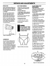
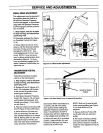
WHEELBRAKEADJUSTMENT
This adjustment may be required if
the m.achine does not hold on a
hillwith the Operator Presence
Control disengaged, or if the brake
drags with the Operator Presence
Control engaged and the transmis-
sion in neutral.
1. Stop engine, wait for all parts
to stop moving, and disconnect
spark plug wire.
2. Disengage (release) the Opera-
tor Presence Control (M, Figure
5-13).
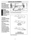
3. Slowly adjust at nut (O), if nec-
essary, untilthe distance between
the back of brake arm (N) and
bracket (P) is 3/8"-5/16". Use
small adjustments (1/4 turn maxi-
mum). NOTE: It may be neces-
sary to relieve spring tension when
decreasing distance. To do so,
have an assistant engage the Op-
erator Presence Control while you
adjust the nut.
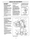
Figure 5-13: Wheel brake adjustment.
3/8_*
5/16"
TRANSMISSIONNEUTRAL
ADJUSTMENT
Follow this procedure to adjust
neutral on the transmission.
1. Stop engine, wait for all parts
to stop moving, and disconnect
spark plug wire.
2. Rotate shift rod (I, Figures 5-14
and 5-15) clockwise until itstops
in the neutral (N) position (from
forward gear positions).
3. Hold down Operator Presence
Control (M, Figure 5-13) and push
unit forward and backward. Unit
should move freely. If not, contin-
ue with Step 4.
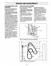
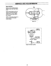
4. Remove cotter pin securing shift
link (P, Figure 5-15) to shift rod (I).
5. Move shift arm (X) back and
forth as necessary into each de-
tent untiltransmission is in neutral.
NOTE: Moving shift arm (X) clock-
wise all the way to the left, and
then one notch back counterclock-
wise, should put transmission
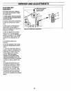
Detentfor Neutral
Position
J
Figure 5-14: Gear Select Lever in neutral (IV)position.
into neutral. When transmission is
in neutral, unit will move freely
when pushed while holding the
Operator Presence Control lever
down. If transmission is NOT in
neutral, there will be a slight drag
on the wheels when pushing unit.
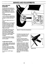
6. When shift arm (X) is in neutral
position, rotate shift link (P) until
hooked end fits back into hole in
bottom end of shift rod (I).
NOTE: Shift rod (I) must be held
in the neutral position (see Figure
5-14) while shift link (P) is
adjusted.
7. Secure shift link (P) into shift
rod (I) with cotter pin removed
earlier.
8. Re-check neutral by pushing
unit back and forth and shifting
lever (I) from re,,_emeto neutral. A
small fine-tune adjustment may be
required.
31