


Turbomachinery Package Specification Titan 250 Generator Set
13 Exhaust System
13.1 General Description
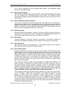
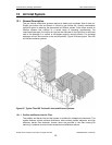
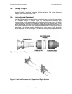
The exhaust system (Figure 25) typically consists of all components installed
downstream of the engine exhaust bellows expansion joint, including silencers and
ducting, that are necessary to ensure a smooth flow of exhaust gas from the engine. The
exhaust duct system must be terminated in a manner that precludes recirculation of
exhaust products through the engine air inlet or oil cooler. Exhaust considerations include
the relative height of the exhaust duct above the air inlet, building roof design, direction of
prevailing winds, and the proximity of adjacent structures. The importance of having an
exhaust system properly designed cannot be overemphasized. A poorly designed
exhaust system can cause loss of power capability and impose severe mechanical
strains on the gas turbine. Exhaust systems should be designed to meet the following
requirements:
• Where two or more units exhaust into a common header, such as used for heat
recovery equipment, provisions must be made to prevent hot gas from flowing
into the non-operating unit (common exhaust ducting is not recommended).
• Final termination of ducting must not allow exhaust gas to be drawn into the gas
turbine inlet.
• Capability to purge the complete exhaust system prior to gas turbine lightoff. For
short simple exhaust systems, purging should be designed to accomplish three
air volume changes. For large complex exhaust systems, purging should be
designed to accomplish five air volume changes either through gas turbine
cranking or supplementary exhaust blowers.
When exhaust silencing is required, provisions must be made to adequately mount and
support the equipment and limit the exhaust silencer pressure loss.
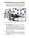
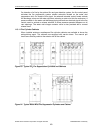
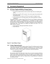
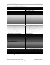
13.1.1 Exhaust Silencer
Solar can provide a silencer with support structure and ducting suitable for connection to
the radial exhaust of the Titan 250 generator set. Brackets are available for mounting the
silencer in a vertical or horizontal position.
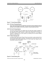
13.2 Turbine Exhaust Heat Recovery System
High thermal efficiencies can be obtained by using the gas turbine exhaust heat energy.
There are several methods for using the exhaust heat and attaining greater than 80% fuel
utilization. The methods used and the efficiencies achieved are primarily dependent on
the type of application. The most common uses are:
1. Producing steam with a heat recovery steam generator (HRSG) or heating a
process fluid with a heat recovery fluid heater.
2. Using the gas turbine exhaust as a source of preheated combustion air in a
boiler or furnace (the gas turbine exhaust contains 15-18% oxygen).
3. Using the gas turbine exhaust directly for a drying or heating process in which
high temperature air is necessary. A mixture of gas turbine exhaust and fresh air
can be used in a reduced air temperature process. An air-to-air heat exchanger
is required when the process involves any products in the human food chain.
Solar can design and provide a complete exhaust heat recovery system to meet specific
application requirements. The system must be designed to minimize the backpressure
imposed on the gas turbine exhaust and provide a smooth flow transition into the exhaust
heat recovery device.
© 2008 Solar Turbines Incorporated. All rights reserved. TPS250GS/908 - Preliminary
55