


Turbomachinery Package Specification Titan 250 Generator Set
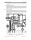
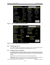
9.3.4 Vibration Monitoring System
The system uses 1701 FieldMonitors and associated sensing devices from Bently
Nevada. The capacity of each monitor is eight vibration channels plus a keyphasor input.
The system is configurable from the control processor. It detects preprogrammed alarm
and shutdown levels. See the specification tables for a list of monitored channels.
9.3.5 Backup Shutdown System
The backup shutdown system shuts the package down in a safe and orderly manner
without damage to the equipment in the event of a failure in the primary system. The
control processor is monitored by both an internal watchdog circuit and by an external
watchdog device. If either circuit detects a processor failure, the backup system takes
control. It opens the generator circuit breaker, closes the fuel valves, and initiates a post
lube cycle to protect the turbine bearings. Once a backup shutdown is initiated, operation
can only be restored manually from the control panel after all faults have been cleared.
The emergency stop push-button switches are wired to both the primary and backup
systems.
9.3.6 Fire and Gas System
Enclosed packages require fire and gas control protection. The Eagle Quantum Premier
system from Det-Tronics detects gas and/or fire inside the enclosure based on inputs
from gas, thermal, and optical flame detectors. If fire is detected, the system releases an
extinguishing agent into the enclosure. If a fire or an unacceptable gas level is detected,
the system instructs the Turbotronic control processor to initiate a package shutdown.
The system is also wired directly to the backup shutdown system. See Enclosure Section
11 for a more complete description.
9.3.7 Combination Generator Control Module
The combination generator control module (CGCM) provides voltage regulation,
automatic breaker synchronization, excitation control, power metering, load sharing, and
protective relay functions. For a more detailed description of the CGCM capabilities, refer
to Section 10, Generator Control and Monitoring.
9.3.8 Control System Power Supplies
The control system operates on 24 VDC power. The standard battery charge system
provides 120 VDC power to the control system. The control system includes a 120 to 24
volt DC-to-DC converter to supply 24 VDC power to the control system. For a more
detailed description of the battery charger system, refer to Section 14, Accessory
Equipment.
9.4 System Monitoring and Control Functions
The control system provides sequencing control during gas turbine startup, steady state
operation, and shutdown. Protective functions are provided during all stages of operation.
9.4.1 Starting and Loading
The Start command initiates the sequence. Prior to rotation, the lube oil pump undergoes
a test cycle, the enclosure fans (if applicable) are started, and the fuel valves undergo a
test cycle with fuel pressure verification.
The starter then rotates the gas turbine and the compressor develops airflow to purge
any accumulated gas in the gas turbine, air inlet, and exhaust duct. The purge cycle is
tailored to the exhaust duct volume.
When the engine has reached the required speed and temperature, a small amount of
fuel is introduced into the combustor from the gas torch and ignited by the ignitor plug.
© 2008 Solar Turbines Incorporated. All rights reserved. TPS250GS/908 - Preliminary
32