


Turbomachinery Package Specification Titan 250 Generator Set
Table of Figures
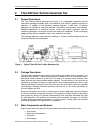
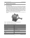
Figure 1. Typical Titan 250 Gas Turbine Generator Set.............................................................6
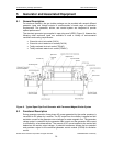
Figure 2. Typical Titan 250 Generator Set Service Connections (Driver Skid) ..........................8
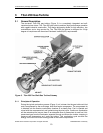
Figure 3. Titan 250 Two-Shaft Gas Turbine Cutaway ..............................................................10
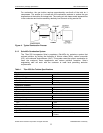
Figure 4. Typical Combustion Process .....................................................................................11
Figure 5. Typical Reduction Gearbox for the Titan 250 Generator Set ....................................13
Figure 6. Typical Open Drip-Proof Generator with Permanent Magnet Exciter System ..........14
Figure 7. Direct-Drive AC Starter Motor and VFD Cabinet.......................................................17
Figure 8. Typical Direct-Drive AC Start System........................................................................18
Figure 9. Turning Gear Assembly.............................................................................................18
Figure 10. Typical Fuel System Schematic ................................................................................21
Figure 11. Typical Lube Oil System............................................................................................26
Figure 12. Typical Onskid Control System..................................................................................30
Figure 13. Typical Offskid Control System..................................................................................30
Figure 14. Turbotronic 4 System Architecture ............................................................................31
Figure 15. Typical TT4000 Operation Summary Display Screen ...............................................35
Figure 16. Typical TT4000 Strip Chart Display...........................................................................35
Figure 17. Typical TT4000S Engine Summary Screen ..............................................................36
Figure 18. Typical TT4000S Generator Summary Screen .........................................................36
Figure 19. Typical Generator, Exciter, and Generator Control Module Arrangement ................41
Figure 20. Typical Generator Metering Panel.............................................................................44
Figure 21. Typical Complete Package Enclosure.......................................................................45
Figure 22. Typical Fire and Gas System.....................................................................................48
Figure 23. Typical CO
2
Fire Suppression Cylinders and Cabinets .............................................49
Figure 24. Typical Water Mist Fire Suppression Cylinders and Cabinet ....................................49
Figure 25. Typical Titan 250 Turbine Air Inlet and Exhaust Systems.........................................52
Figure 26. Typical Battery Charger.............................................................................................57
Figure 27. Turbine Cleaning System ..........................................................................................58
Figure 28. Turbine Cleaning Cart................................................................................................58
Figure 29. Separation of Engine Sections ..................................................................................59
Figure 30. Rails and Fixtures for Axial Separation of Engine Sections ......................................59
© 2008 Solar Turbines Incorporated. All rights reserved. TPS250GS/908 - Preliminary
4