


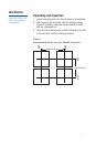

4
Wiring
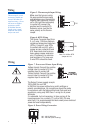
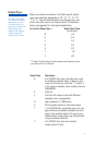
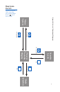
Figure 5. Thermocouple Input Wiring
Make sure that you are using
the appropriate thermocouple
and extension wire. Connect the
negative lead (generally colored
red in ISA-type thermocouples)
to contact #9; connect the
positive lead to contact #10.
Extension wires must be the
same polarity as the thermo-
couple.
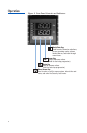
Figure 6. RTD Wiring
The Series C accepts input from
2- or 3-wire, 100 ohm platinum
resistance temperature detectors
(RTDs). Connect 2-wire RTDs
to contacts #9 and #10, with a
jumper across contacts #8 and
#10. Keep leads short and use
heavy gauge copper extension
wire, if necessary, to minimize
lead resistance. For long runs,
3-wire RTDs should be used.
Thermocouple circuit
resistance should not
exceed 100 ohms for
rated accuracy; errors
will occur at higher
resistance values.
If shielded thermo-
couple wire is used,
terminate the shield
only at one end.
8
9
10
RTD
8
9
10
T/C
Note: For 2-Wire RTD
Jumper 8 & 10
Wiring
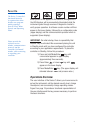
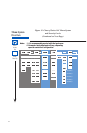
Figure 7. Process and Linear Input Wiring
Voltage Inputs: Connect the positive
voltage input to contact #10; the
negative input to contact #9.
Current Inputs: Connect the positive
current input to contact #10; the
negative input to contact #9.
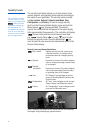
The Series C power supply accepts
100 to 250 Vac and 100
to 250 Vdc line power without any switch settings or
polarity considerations. All connections should be made
in accordance with the National Electrical Code and local
regulations, using only NEC Class 1 wiring for all power
terminals.
It is advisable, but not necessary, to fuse one leg of the
incoming power line, contact #11, with a 2AG, 0.5 amp
rated fuse. It is recommended that instrument power and load
power be fused independently.
Figure 8. Power Wiring Connection
3
4
5
8
9
10
11
12
L1 L2
100 - 250 V 50/60 Hz
100 - 250 Vdc (Auto Polarity)