


2
3
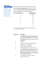
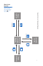
Wiring
IMPORTANT: All electrical wiring connections should be made
only by trained personnel, and in strict accordance with the
National Electrical Code and local regulations.
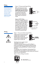
The Series C controller has built-in circuitry to reduce the
effects of electrical noise (RFI) from various sources.
However, power and signal wires should always be kept
separate. We recommend separating connecting wires into
bundles: power; signal; alarms; and outputs. These bundles
should then be routed through individual conduits. Shielded
sensor cables should always be terminated at one end only.
If additional RFI attenuation is required, noise suppression
devices such as an R.C. snubber at the external noise source
may be used. If you wish, you may order this suppressor
directly from Athena, part number 235Z005U01.
1
2
3
4
5
6
7
8
9
10
13
14
11
12
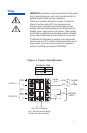
N.O.
C
N.C.
N.O.
C
SENSOR
INPUT
T/C
OUTPUT 1
OUTPUT 2
RT
D
L1 L2
100 - 250 V 50/60 Hz
100 - 250 Vdc (Auto Polarity)
24 Vac/Vdc (Auto Polarity)
A2
232/485
GND
ALARM
&
COMM.
COM
N.O.
N.O.
RCV
B (-)
COM
XMT
A (+)
A1
RS 232
RS 485
ALARM & COMM.
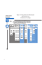
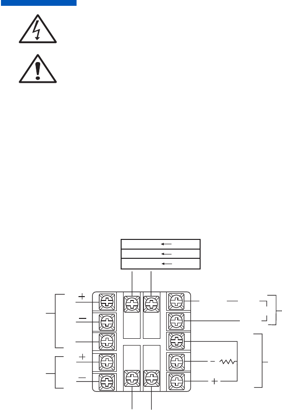
Figure 4. Contact Identification