


Service Addendum46
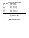
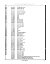
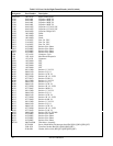
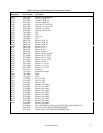
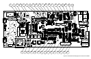
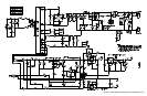
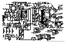
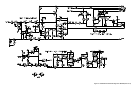
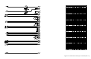
A1 Main Board Schematics (Figure 6-5)
The four schematic sheets for the A1 board included in this addendum replace
figures 6-2 and 6-5 in the standard Service Manual for the Agilent Series 665xA DC
Power Supplies.
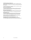
The assembly drawing for the A1 main board included in this addendum replaces
Figure 6-5 in the standard Service Manual.
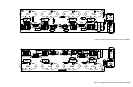
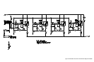
Left Tunnel Circuits (Figure 6-6)
The component locations and schematic drawings for the A4 left tunnel circuits
included in this addendum replace figure 6-6 in the standard Service Manual.
Right Tunnel Circuits (Figure 6-7)
The component locations and schematic drawings for the A4 right tunnel circuits
included in this addendum replace figure 6-7 in the standard Service Manual.
DSP Board (Figure 6-10)
The simplified component locations diagram for the A5 DSP board shows the
location of the troubleshooting test points on the J721 and J722 connectors
as well as the location of the two replaceable ROM chips, U734 and U735.
Because troubleshooting for the A5 DSP Board is to the assembly level only,
no schematics or parts lists are included for this board.
Adapter Board and Phone Adapter Board (Figures 6-11, 6-12)
The A6 Adapter board connects the A5 DSP board to the A1 main board.
The A7 Phone Adapter board connects the A5 DSP board to the A2 GPIB board.