


Service Addendum4
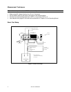
Measurement Techniques
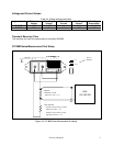
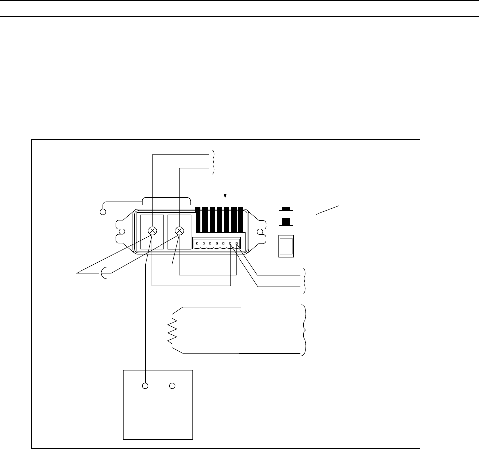
Note All tests are performed in the FIXED as shown in Figure 2-1.
• Measure the DC voltage directly at the +S and -S terminals.
• Set the SENSE switch at the back of the supply to the Remote position.
• Connect the remote sensing leads from +OUT to +S, and from -OUT to -S.
• Use adequate wire gauge for the load leads as described in Chapter 4 of the Operating Manual.
Basic Test Setup
Figure 2-1. Basic Test Setup
+
-
+
IM
-
IMIP
+
S
-
S
+240 VDC MAX
-
VP I P
SET TO
REMOTE
REMOTE
LOCAL
TO OSCILLOSCOPE
OR RMS VOLTMETER
+
-
*
ELECTRONIC
LOAD
CURRENT MONITORING
RESISTOR
(GUILDLINE 0.1 OHM,
TO DVM
TO DVM OR
RMS VOLTMETER
(CC TESTS)
* USE DC POWER SUPPLY
(SAME POLARITY CONNECTIONS)
FOR -CC TEST
15 A, 0.04%)
120 uF, 100 V
+