


Service Addendum 43
Chapter 6 Differences
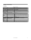
Test Points
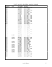
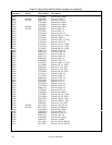
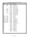
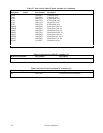
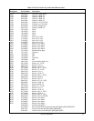
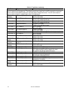
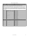
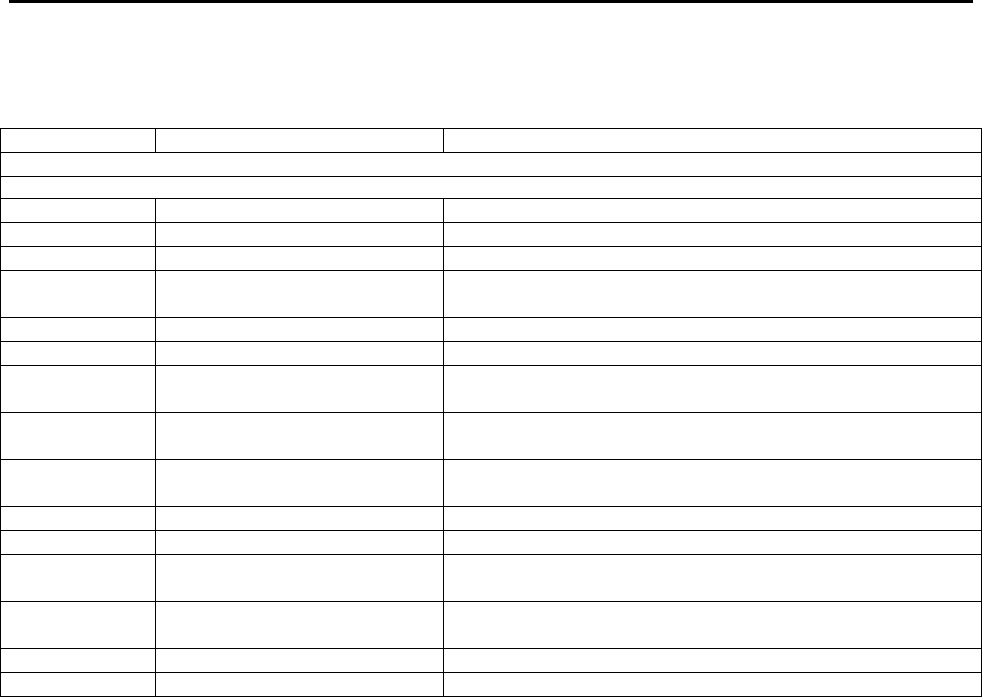
Table 6-3. Test Points
Test Point Signal Measurement and Conditions
A1 Main Board (Sheets 1-4); A5 DSP Board
Connect meter or scope common to Test Point (TP) 9 when taking measurements at Test Points 10 through 46
TP9 R703-3 Secondary common (sheet 1) R703-3 (RmINB)
TP10 F703 +5V Sec Bias (sheet 1) +5V +/- 0.2V
TP11 R704 +15 Sec Bias (sheet 1) +15 +/- 0.6V
TP12 Q700
(heat sink)
+24V (sheet 1) +21V to +27V (1V p-p ripple)
TP13 R708 -15V Sec Bias (sheet 1) -15V +/- 1V
TP14 U701-2 -25V (sheet 1) -22V to –28V (300mV p-p ripple)
TP15 U702-3 Fan speed control (sheet 1) +3V with no load connected and ambient temperature
25C.
TP16 D701
anode
Fan speed control (sheet 1) +2.95V with no load connected and ambient temperature
25C.
TP17 U603-5 PCLR* (DSP Board) (sheet 3) Goes low for approximately 40mS at power on, then goes
high (5V).
TP18 U603-7 Shutdown circuit (sheet 3) +8.69V with output on
TP19 U602-16 Shutdown circuit (sheet 3) +0.7V with output off, +15.2V with output on.
TP20 VR602
anode
+9V Gated (sheet 3) +9V
TP21 D606
anode
-15V Gated(sheet 3) -14.2V
TP24 R421 CC_Prog (sheet 2) -4.2V (approximate) with full-scale current programmed.
TP25 R623 CV_Prog (sheet 2) -4.3V (approximate) with full-scale voltage programmed.