


16 Assembly
MAN0169 (Rev. 5/6/2005)
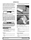
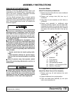
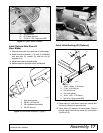
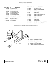
4. Secure rear blade frame assembly to pivot
assembly using pivot cap (3), two hardened flat
washers (25), and hex nuts (24).
5. Place rear blade frame assembly in desired
position and secure with hitch pin (8).
6. Place parking stand in the down position to support
rear blade. See page 11 for storage.
Figure 13. Rear Blade Frame to Pivot Assembly
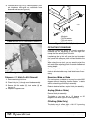
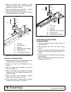
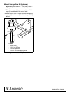
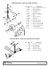
Assembly Landscape Rake
1. Place jack stands or suitable blocking device under
tine beam so pivot tube is pointing upward.
2. Remove pivot cap (3) and hardware from tine
beam (1).
3. Place rear blade frame assembly (9) over pivot
tube on tine beam (1).
4. Secure rear blade frame assembly to tine beam
using pivot cap (3), two hardened flat washers (25),
and hex nuts (24).
5. Place rear blade frame assembly in desired
position and secure with hitch pin (8).
6. Place parking stand in storage position to support
landscape rake. See page 11 for storage.
Figure 14. Landscape Rake Assembly
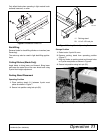
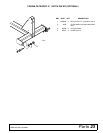
Install Optional Caster Wheels
(Landscape Rake)
1. Remove landscape rake from tractor 3-point lift
arms if attached.
2. Roll landscape rake over with tines pointing
upward.
3. Place jack stands or suitable blocking device under
tine beam to raise tine beam approximately 8 to 10
inches.
4. Place tail wheel arm (9) between lugs on tine beam
and align holes.
5. Secure into position using three cap screws (13)
and flange lock nuts (12).
9
6
CD6155A -1
3
25
24
8
3. Pivot cap
6. Pivot assembly
8. Hitch pin
9. Rear blade frame assembly
24. 5/8 NC Hex nut
25. 5/8 Hardened flat washer
3
25
24
8
1
9
CD6155B-2
1. Tine beam
3. Pivot cap
8. Hitch pin
9. Rear blade frame assembly
24. 5/8 NC Hex nut
25. 5/8 Hardened flat washer