


Maintenance 13
MAN0169 (Rev. 5/6/2005)
MAINTENANCE
The information in this section is written for operators
who possess basic mechanical skills. If you need help,
your dealer has trained service technicians available.
For your protection, read and follow all safety informa-
tion in this manual.
Before dismounting power unit or performing
any service or maintenance, follow these steps:
disengage power to equipment, lower the 3-point
hitch and all raised components to the ground,
operate valve levers to release any hydraulic pres-
sure, set parking brake, stop engine, remove key,
and unfasten seat belt.
NEVER GO UNDERNEATH EQUIPMENT. Never
place any part of the body underneath equipment
or between moveable parts even when the engine
has been turned off. Hydraulic system leak down,
hydraulic system failures, mechanical failures, or
movement of control levers can cause equipment
to drop or rotate unexpectedly and cause severe
injury or death.
• Service work does not require going under-
neath.
• Read Operator's Manual for service instruc-
tions or have service performed by a qualified
dealer.
Keep all persons away from operator control
area while performing adjustments, service, or
maintenance.
Always wear relatively tight and belted clothing
to avoid entanglement in moving parts. Wear
sturdy, rough-soled work shoes and protective
equipment for eyes, hair, hands, hearing, and head;
and respirator or filter mask where appropriate.
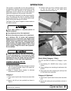
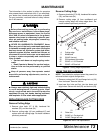
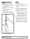
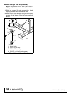
REPLACING BLADE CUTTING EDGE
Remove Cutting Edge
1. Remove plow bolts (27 & 28), hardened flat
washers (25), and hex nuts (24).
2. Remove cutting edge (4) from moldboard (5) and
replace with new cutting edge. Re-install hardware
previously removed.
Reverse Cutting Edge
1. Remove plow bolts (27 & 28), hardened flat washer
(25), and hex nuts (24).
2. Remove cutting edge (4) from moldboard and
reverse cutting edge with sharp edge down. Re-
install hardware previously removed.
Figure 9. Cutting Edge Replacement
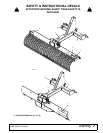
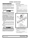
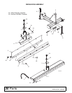
LRC60 TINE REPLACEMENT
NOTE: Tines should be replaced when they cannot be
reformed to their original configuration.
1. Remove carriage bolt (22) and flange lock nut (23)
from tine beam. Remove old tine.
2. Inset new tine, hole end first, into tine beam and
align holes. Secure with bolt (22) and lock nut (23).
Figure 10. Rake Tine Replacement
CAUTION
4
5
24
25
27
28
CD6156-3
4. Cutting edge
5. Moldboard
24. 5/8 NC Hex nut
25. 5/8 Hardened flat washer
27. 5/8 NC x 1-1/2 Plow bolt
28. 5/8 NC x 2 Plow bolt
2
22
23
CD6156-4
2. Rake tine
22. 3/8 NC x 1 Carriage bolt
23. 3/8 NC Flange lock nut