


Assembly 15
MAN0169 (Rev. 5/6/2005)
ASSEMBLY INSTRUCTIONS
DEALER SET-UP INSTRUCTIONS
Assembly of this Rear Blade/Landscape Rake is the
responsibility of the WOODS dealer. It should be deliv-
ered to the owner completely assembled, lubricated
and adjusted for normal cutting conditions.
The Rear Blade/Landscape Rake is shipped partially
assembled. Assembly will be easier if components are
aligned and loosely assembled before tightening hard-
ware. Recommended torque values for hardware are
located on page 24.
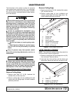
Before dismounting power unit or performing
any service or maintenance, follow these steps:
disengage power to equipment, lower the 3-point
hitch and all raised components to the ground,
operate valve levers to release any hydraulic pres-
sure, set parking brake, stop engine, remove key,
and unfasten seat belt.
NEVER GO UNDERNEATH EQUIPMENT. Never
place any part of the body underneath equipment
or between moveable parts even when the engine
has been turned off. Hydraulic system leak-down,
hydraulic system failures, mechanical failures, or
movement of control levers can cause equipment
to drop or rotate unexpectedly and cause severe
injury or death.
• Service work does not require going under-
neath.
• Read Operator's Manual for service instruc-
tions or have service performed by a qualified
dealer.
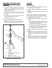
Keep all persons away from operator control
area while performing adjustments, service, or
maintenance.
Always wear relatively tight and belted clothing
to avoid entanglement in moving parts. Wear
sturdy, rough-soled work shoes and protective
equipment for eyes, hair, hands, hearing, and head;
and respirator or filter mask where appropriate.
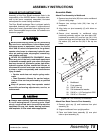
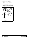
Assemble Blade
Attach Pivot Assembly to Moldboard
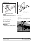
1. Remove two plow bolts (28) from center moldboard
(5) and cutting edge.
2. Remove two carriage bolts (26) from top of
moldboard.
3. Align holes on pivot assembly (6) with holes on
moldboard.
4. Secure pivot assembly to moldboard using
hardware previously remove. Use plow bolts (28),
hardened flat washer (25), and hex nut (24) in the
bottom two holes and carriage bolts (26), hardened
flat washer (25), and hex nut (24) in the top two
holes.
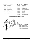
Figure 12. Pivot Assembly to Moldboard
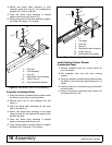
Attach Rear Blade Frame to Pivot Assembly
1. Remove pivot cap (3) and hardware from pivot
assembly (6).
2. Support moldboard in an upright position.
3. Place rear blade frame assembly (9) over pivot
tube on pivot assembly (6).
CAUTION
5
6
2
6
2
5
2
4
2
8
2
5
24
C
D
6
1
56
-
2
5. Moldboard
6. Pivot assembly
24. 5/8 NC Hex nut
25. 5/8 Hardened flat washer
26. 5/8 NC x 1-1/2 Carriage bolt GR5
28. 5/8 NC x 2 Plow bolt