


10 Operation
MAN0169 (Rev. 8/26/2005)
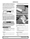
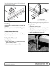
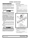
3. Connect tractor top link by inserting tractor clevis
pin into lower hitch point on rear blade frame
assembly and secure (Figure 4).
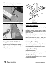
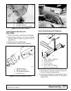
Figure 3. Lower Lift Arm Attachment, Category 0
Figure 4. Top Link Connection
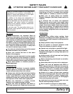
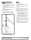
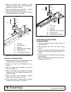
Category 0 / 1 Hitch Pin Kit (Optional)
1. Remove existing hitch pins.
2. Place hitch pin (1) through rear blade assembly.
3. Secure with flat washer (2), lock washer (3) and
hex nut (4).
4. Repeat for opposite side.
Figure 5. Hitch Pin Kit (Optional)
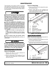
OPERATING TECHNIQUES
Level the A-frame and boom with 3-point connecting
links and top link. Adjusting the top link length will
change the fore and aft pitch of the tool.
Lengthening the top link will cause the tool to contact
the ground with a sharper pitch and feed itself into the
ground more readily.
When using the rake tool, you may need to adjust the
tail wheels after adjusting pitch to maintain the desired
working depth.
Position 3-point lift arm sway blocks or tighten sway
chains to eliminate side sway. Install side braces if nec-
essary.
Reversing (Blade or Rake)
For most tractors, the blade or rake may be rotated 360
degrees without unhooking from the tractor. To rotate
without unhooking, pull hitch pin assembly.
Rotate to desired position; replace hitch pin assembly.
Angling (Blade or Rake)
Remove hitch pin assembly.
The blade or rake may be set 15 degrees or 30
degrees to the left or right for forward grading.
Offsetting (Blade Only)
The blade may be offset right or left 12" by moving
moldboard on pivot assembly.
DP6
CD6625
1
2
3
4
1. Hitch pin
2. 7/8 Flat washer
3. 7/8 Lock washer
4. 7/8 Hex nut