


24 Assembly
32695 (Rev. 11/17/2006)
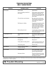
When checking tension without a force measuring
device, the belt, when properly set, should feel very
tight.
Cycle belt through at least two revolutions after any
adjustment before checking tension. These belts are
very strong and need to be adjusted very tightly. Belts
are more likely to be damaged by excessive slippage
than from being overtightened.
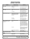
Minor tension adjustments are made by moving the
idler pulleys up or down. Major tension adjustments are
made by moving the mower deck forward and rear-
ward.
IMPORTANT
■ Alignment must be rechecked if it is necessary
to move idler pulleys or the mower deck to get
proper belt tension.
■ Tension on a new belt should be readjusted
every half hour for the first two hours and then
checked every eight hours of operation.
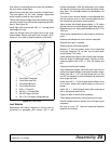
Rear Belt Shield Installation
Place stud welded on bottom of belt shield in small
front hole of idler bracket drawbar.
Install clevis pin through belt shield brackets and top
link bracket.
Secure with safety pin.
OPTIONAL EQUIPMENT
A leaf mulcher, low suction blades, extra-suction
blades, front roller and casters are offered as optional
equipment for this mower. Some options may not be
available for some mountings.
Blades
Low suction and extra suction blades are optional for
this mower. In sandy areas where abrasive action
could cause excessive blade wear, low suction blades
are recommended.
Extra suction blades are designed to lift up fragile
downed grasses for better cutting results. They are
also recommended for use with leaf mulcher attach-
ment.
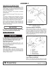
Casters
Casters are used to adjust cutting height.
Mount casters on mowers to the outside deck rails and
over side shield or discharge chute. Attach rear of
caster arm in fourth hole from front of deck rail with a
3/8" x 1-1/2" bolt and secure with lock washer and nut.
The arm may be mounted in the third hole to obtain
more height and caster adjustment.
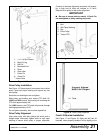
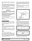
Attach the right and left adjustment brackets, offset
down and inward, and in front hole as shown in Figure
25 on each side of the deck angle and inside side skid.
Use two 1/2" flat washers as spacers at the rear side
skid hole.
Select the desired cutting height and install adjustment
brackets to caster arm with 1/2" x 1-3/4" bolts and
secure with 1/2" flange lock nuts.
Adjust side skids to ride at least 1/2" above ground
level.
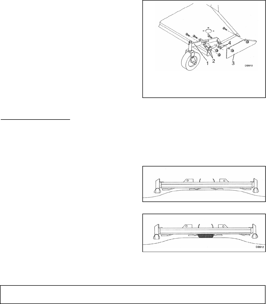
Figure 25. Caster Assembly
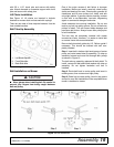
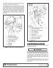
Front Roller
The front roller should be used when scalping occurs.
Side skids and casters effectively reduce scalping in
most cases. You may encounter areas where the side
skids or casters will drop into depressions and allow
the center of the mower to contact the ground and
scalp. When this occurs you should install a front roller
in the center of the mower.
Figure 26. Scalping Without Front Rollers
Figure 27. Front Rollers Reduce Scalping
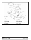
See Figure 28. Place and secure mower in vertical
position to make front roller installation easier.
1. Caster Arm
2. Adjustment Brackets
3. Side Shield