


Assembly 21
32695 (Rev. 11/17/2006)
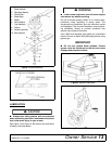
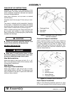
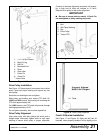
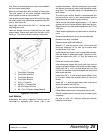
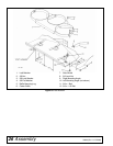
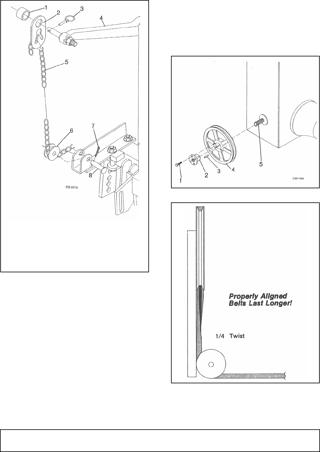
Figure 14. Rear Lift Installation
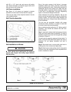
Drive Pulley Installation
See Figure 15. Remove paint from center hole of drive
pulley. Insert split taper bushing and square key into
drive pulley.
Start bolts into bushing but do not tighten.
Slide pulley and bushing onto tractor PTO shaft. On
L2250 and 2550 tractors, the bushing will overhang the
PTO shaft approximately 3/8".
On L2850 tractors, the PTO shaft will protrude through
bushing approximately 15/16".
Do not tighten assembly; belt must be aligned first.
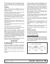
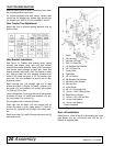
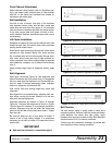
Drive Pulley Alignment
Align drive pulley with idler pulleys and check with a
straight edge. Alternately tighten bolts on split taper
bushing to secure drive pulley in proper alignment.
Continue to alternate tightening sequence until assem-
bly is tight and all bolts are torqued to 12 lbs-ft.
Recheck drive pulley to idler pulley alignment.
IMPORTANT
■ Be sure to torque bolts to exactly 12 lbs-ft. Do
not overtighten or pulley casting may crack.
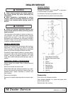
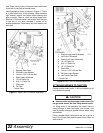
Figure 15. Drive Pulley Installation
Figure 16. Drive Pulley Alignment
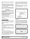
Front Lift Bracket Installation
See Figure 17 and Figure 18. Right and left front lift
brackets, when properly installed, will tip slightly to the
1. 1 x 1-1/4 Pipe Sleeve
2. Rear Lift Lug
3. Klik Pin*
4. Rockshaft Arm*
5. Chain
6. Chain Idler
7. Cotter Pin
8. Clevis Pin
* Tractor Parts
1. Bolt
2. Split Taper Bushing
3. Key
4. Drive Pulley
5. Tractor PTO